


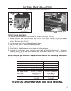

GAS LINE CONNECTION:
an access hole of 1.5 in (37.5mm) or less may be drilled through the lower sides or bottom of the rebox
in a proper workmanship like manner. This access hole must be plugged with non-combustible insulation
after the gas supply line has been installed.”
• A shut-off valve is not supplied with this unit but one should be installed.
• The appliance and its shut-off valves must be disconnected from the gas supply piping system during
any pressure testing where the pressure exceeds psig (3.45 KPa) or the valve will be damaged.
• The unit must be isolated from the gas supply piping system by closing its individual manual shut off
valve during any pressure testing of the gas supply piping system at pressures equal to or less than
psig (3.45 KPa).
Warning: Only persons licensed to work with gas piping may
make the necessary gas connections to this appliance.
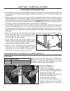
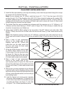
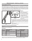
Gas Line Connection:
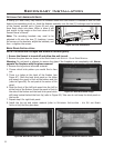
• A ” NPT male pipe will have to be turned into the ” NPT
female elbow at the lower right side rear of this replace (see
Figure 53). Consult the local authorities for local codes or use the
CAN/CGA B149 (1 or 2) installation code in Canada. In the US, gas
installations follow either local codes or the current edition of the
National Fuel Gas Code ANSI Z223.1.
• The efciency of this unit is a product thermal efciency rating
determined under continuous operating conditions and was
determined independently of any installed system.
• If the factory-built replace has no gas access hole(s) provided,
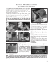
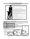
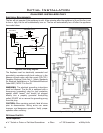
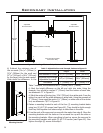
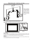
Figure 52. Remove/Install Control Panel.Figure 51: Grounding Power Cord.
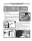
11. Make note of the order the connectors are in on the
three (3) position switch and remove them. Slide the
switch through the front of the hole that was just
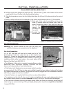
8. Pull the control panel straight out (see Figure 52). There are two (2) tabs on the bottom of the control
panel that t in two (2) slots in the Sonnet cabinet bottom.
9. Slide the temperature sensor into the holding tabs below the left end of the burner behind the control
panel.
10. Using a utility knife cut out the rectangle on the control panel between the two (2) fan symbols.
Ground
Initial Installation
QUALIFIED INSTALLERS ONLY
cut out and
reattach the
connectors to
the switch.
12. Re-install the
control panel.
Thermocouple
3/8” NPT
Female Elbow
Pilot Line
Figure 53: ” NPT female elbow.
26