


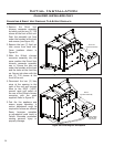
Initial Installation
QUALIFIED INSTALLERS ONLY
GAS LINE CONNECTION:
Warning: Only persons licensed to work with gas piping may make the necessary gas connections to
this appliance.
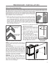
Gas Line Connection:
•This replace is equipped with a certied exible pipe located on the right side of the unit, terminating
in a ” male NPT tting. Consult the local authorities for local codes or use the CAN/CGA B149 (1 or 2)
installation code in Canada. In the US, gas installations follow either local codes or the current edition of
the National Fuel Gas Code ANSI Z223.1.
•The efciency of this unit is a product thermal efciency rating determined under continuous operating
conditions and was determined independently of any installed system.
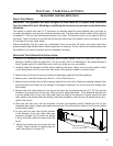
The appliance and its appliance main gas valve
must be disconnected from the gas supply piping
system during any pressure testing of that system
at test pressures in excess of psi (3.5 kPa).
The appliance must be isolated from the gas
supply piping system by closing its equipment
shutoff valve during any pressure testing of the
gas supply piping system at test pressures equal
to or less than psi (3.5 kPa).
The unit must be isolated from the gas supply
piping system by closing its individual manual
shut off valve during any pressure testing of the
gas supply piping system at pressures equal to
or less than psig (3.45 KPa).
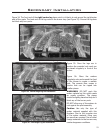
O
L
I
T
P
TP TH TP TH
IN OUT
H
I
L
O
N
O
F
O
F
L
I
P
T
O
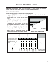
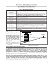
Main Burner Natural Gas Propane Gas
Orice: #32 DMS #49 DMS
Venturi Setting: ” Min. ” Min.
Manifold Press: 3.8 W.C. (0.95 KPa) 11.0 W.C. (2.74 KPa)
Min. Manifold Press: 1.2 W.C. (0.30 KPa) 2.7 W.C. (0.67 KPa)
Max. Supply Press: 7.0 W.C. (1.74 KPa) 13.0 W.C. (3.28 KPa)
Min. Supply Press: 5.0 W.C. (1.24 KPa) 12.0 W.C. (2.98 KPa)
Max. Input: 41,000 BTU/hr
(12.0 KW)
41,000 BTU/hr
(12.0 KW)
Min. Input: 23,000 BTU/hr
(6.7 KW)
21,000 BTU/hr
(6.1 KW)
Always check for gas leaks with a soap
and water solution after completing the
required pressure test.
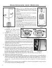
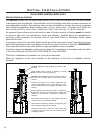
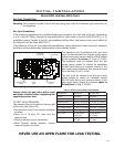
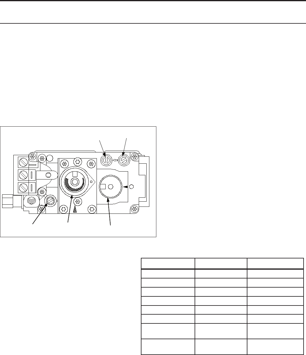
TO TEST VALVE PRESSURES:
The pressure taps are located on the top right
of the valve (see Figure 24).
• Turn set screw one (1) turn counter-clockwise
to loosen.
• Place
5
/16 in (8 mm) I.D. hose over the
pressure taps.
• Check pressures using a manometer.
• When nished, release pressure, remove
hose and tighten set screw.
NEVER USE AN OPEN FLAME FOR LEAK TESTING.
Figure 24: Fully labeled gas valve.
Table 5: Orice and Pressure Information.
19