


Initial Installation
QUALIFIED INSTALLERS ONLY
INSTALLATION OF APPLIANCE:
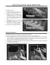
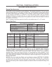
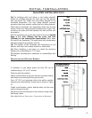
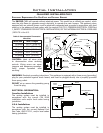
Sealant
Female
Locking
Lugs
Male
Locking
Lugs
Figure 26: Twist-Lock
Connection.
- PO512-54 DMS). Refer to MAINTENANCE AND SERVICE - FUEL CONVERSION.
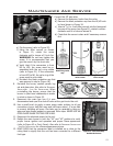
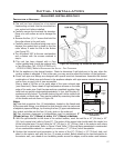
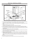
3. Set the appliance in the desired location. Check to determine if wall studs are in the way when the
venting system is attached. If this is the case, you may want to adjust the location of the appliance.
4. Direct vent pipe and ttings are designed with special twist-lock connections. Assemble the desired
combination of black pipe and elbows to the appliance adapter with pipe seams oriented towards the
wall or oor, as much out of view as possible.
17
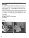
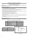
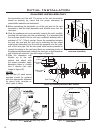
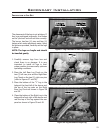
Figure 25: Converting Top Vented into Rear Vented.
Venting
Gasket
Rotate 180
o
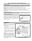
1. This unit has been shipped as a top-vented
freestanding unit and must be converted to a
rear vented unit before installed.
a. Carefully remove the trivet and the stovetop.
Place on a soft surface as not to damage the
nish.
b. Remove the four (4) ” screws that hold the
ue collar elbow to the unit body.
c. Carefully remove the elbow being sure not to
damage the gasket that is glued to the ue
collar elbow, it seals the ue to the rebox
(see Figure 25).
d. Turn the elbow 180° to the rear vent position
and re-fasten with the screws removed in
step b.
2. This unit has been shipped with a Cara
orice installed and it must be replaced with
a Cara DR orice (NG - PO512-42 DMS or LP
Place a bead of Mil-Pac on the outer edge of the inner exhaust pipe
(non-ared end). Place a bead of high temperature silicone on the male
edge of the outer pipe. Push the pipe sections completely together, then
twist-lock one section clockwise approximately turn, until the two (2)
sections are fully locked. The female locking lugs will not be visible from
the outside, on black pipe. They may be located by examining the inside
of the female ends as shown in Figure 26.
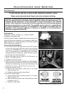
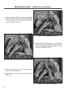
Notes:
(a) Twist-lock procedure: four (4) indentations, located on the female end
of the pipes and ttings, are designed to slide straight onto the male ends
of adjacent pipes and ttings, by orienting the four (4) pipe indentations so
they match and slide into the four (4) entry slots on the male end.
(b) Pipe minimum clearances to combustibles must be maintained; 2”
(51mm) at top, 1” (38mm) at sides, 1” (38mm) at bottom.
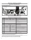
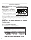
3. With the pipe attached to the stove in the correct location, mark the wall for a 10” (25.4cm) x 10”
(25.4 cm) square hole (refer to Figure 27). The center of the square hole should match the center line
of the horizontal pipe. Cut and frame the 10” (25.4cm) x 10” (25.4cm) hole in the exterior wall where
the vent will be terminated. Refer to Figure 24 and Table 7. If the wall being penetrated is constructed
of non-combustible material i.e. masonry or concrete, a 7” (17.8cm) hole is acceptable.
4. Position the horizontal vent termination in the center of the 10” (25.4cm) x 10” (25.4cm) hole, and
attach to the exterior wall with the four (4) screws provided. Before attaching the vent termination to
the exterior wall, run a bead of non-hardening mastic around the edges, so as to make a seal between