


18
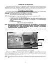
MAINTENANCE
CAUTION: UNPLUG THE UNIT PRIOR TO ANY SERVICE WORK!
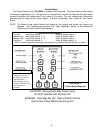
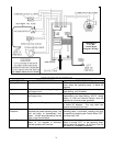
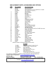
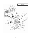
SEE EXPLODED DIAGRAM (ILLUSTRATION 6) FOR PARTS REFERENCE
Note: To do any service on this unit the rear access sheet metal panel must
be removed. One (1) screw holds this panel to the rear of the stove.
Parts Orders: (800) 516-3636 www.englanderstoves.com Questions: (800) 245-6489
Visit our web site for information that details and illustrates the following maintenance tasks.
Auger Motors
The Auger Motor and gearbox are one complete assembly, and can be removed by
disconnecting the power leads and loosening the (
5
/
16
” head) set bolt in front of the assembly. This
bolt tightens down on the flat side
of the gear shaft and locks the gear shaft and auger shaft together
– once the bolt is loosened, the entire assembly will slide from the locking collar. There are two motor
assemblies on the unit, and both rest on a shelf when not in operation. When replacing a motor, the
assembly should always be placed to rest on this shelf prior to starting the unit.
Convection Blower
The Convection (room air) Blower (Part # PU-4C447) can be removed by disconnecting the
power leads and removing the four mounting screws. Once this is done, the blower will slide out of
the stove. This procedure can be reversed to install a new blower.
Combustion Blower
To clean or replace the Combustion (exhaust) Blower (Part # PU-076002B), the power leads
from the blower and the corn vent pipe must be disconnected. Next, remove the screws that hold the
blower to the steel exhaust tube and slide the blower from the stove. The blower impeller, blower
tube and steel blower exhaust tube on the unit should be brushed and vacuumed. When cleaning or
replacing the blower a new gasket (Part # PU-CBG) should be added between the blower flange and
the steel exhaust tube.
Vacuum Switch
The vacuum switch (Part # CU-VS) is located above the stirrer drive motor and shuts the feed
auger off when the fuel door is left open or the combustion blower fails. If an operational error
occurs in the unit, the switch will stop the feed auger. Situations which could cause this include
power failure, Combustion Blower failure, improper flue installation, a blocked flue (from rodents,
nests, etc.), or “dirty burning” from burning improper fuel (see “Important Information” at the
beginning of the manual).
Gaskets
IMPORTANT: IMPROPER GASKET MAINTENANCE, INCLUDING FAILURE TO REPLACE
GASKETS, CAN CAUSE AIR LEAKS RESULTING IN SMOKE-BACKS.
This unit comes with a 5/8” rope gasket around the door that should be replaced at least every
two years. To replace the door gasket (Part # AC-DGKNC), the old gasket must first be removed
entirely — prior to adding the new adhesive, you may have to scrape the old cement from the door
channel. Once the cement and gasket have been added, the door should be closed and latched for
twenty-four hours to allow the cement to harden.
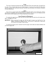
If you are replacing the window gasket (Part # AC-GGK), the new gasket will already have
adhesive on one side. Remove the paper on the adhesive side and place the gasket around the
outside edge of the glass by forming a “U” with your fingers and placing the gasket around the glass.
You should also replace the Combustion Blower gasket (Part # PU-CBG) whenever you remove or
clean the Combustion Blower.