


15
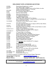
Convection Blower
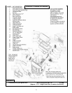
The Convection (room air) Blower (Part # PU-4C447) is located on the left side of the unit and
can be removed by disconnecting the power leads and removing the four mounting screws. Once
this is done, the blower will slide out of the stove. This procedure can be reversed to install a new
blower.
Combustion Blower
To clean or replace the Combustion (exhaust) Blower (Part # PU-076002B), the power leads
and the pellet vent pipe must be disconnected. Next, remove the screws that hold the blower to the
steel exhaust tube and slide the blower from the stove. The blower impeller, blower tube and steel
blower exhaust tube on the unit should be brushed and vacuumed. When cleaning or replacing the
blower a new gasket (Part # PU-CBG) should be added between the blower flange and the steel
exhaust tube.
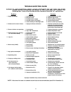
Vacuum Switch
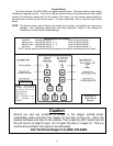
This unit is equipped with Vacuum Shut Down Switches (Part # PU-VS and CU-VS), which help
control various functions of the unit. If an operational error occurs in the unit, a switch will either
stop the top (feed) auger or shut the unit off; if the unit turns off an E-1 Code (error code) will
appear in the Heat Range and Blower Speed windows of the Control Board. Situations which could
cause this include power failure, Combustion Blower failure, improper flue installation, a blocked
flue (from rodents, nests, etc.), or “dirty burning” from burning improper fuel (see “Important
Information” at the beginning of the manual).
Gaskets
IMPORTANT: IMPROPER GASKET MAINTENANCE, INCLUDING FAILURE TO REPLACE
GASKETS, CAN CAUSE AIR LEAKS RESULTING IN SMOKE-BACKS.
This unit comes with a 3/4” rope gasket around the door that should be replaced every two
years. To replace the door gasket (Part # AC-DGKC), the old gasket must first be removed entirely
— prior to adding the new adhesive, you may have to scrape the old cement from the door channel.
Once the cement and gasket have been added, the door should be closed and latched for twenty-
four hours to allow the cement to harden.
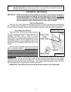
If you are replacing the window gasket (Part #AC-GGK), the new gasket will already have
adhesive on one side. Remove the paper on the adhesive side and place the gasket around the
outside edge of the glass by forming a “U” with your fingers and placing the gasket around the
glass. You should also replace the Combustion Blower gasket (Part # PU-CBG) whenever you
remove or clean the Combustion Blower.
Finish
This new unit has been painted with High-Temperature Paint (AC-MBSP) that should retain its
original look for years. If the unit should get wet and rust spots appear, the spots can be sanded
with plain steel wool and repainted. We recommend this paint, as others may not adhere to the
surface or withstand the high temperatures.
Glass
This unit has a 9” x 9” ceramic glass (Part #AC-G9, comes with gasket) in the viewing door.
Surface scratches are acceptable and normal, but if this glass becomes cracked in any area, the
unit should be shut down and the window replaced with this high-temperature ceramic glass.