


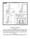

INSTALLATION INTO A MASONRY FIREPLACE
Always follow Local Codes!
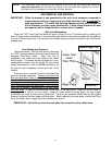
1. Measure your hearth to be sure it is large enough to accept the unit. The hearth should be twelve
inches (12”) from the face of the fireplace to the edge and at least thirty-six inches (36”) wide.
The unit requires eighteen inches (18”) of protection in front of the firebox. If you do not have
enough space, it can be achieved with a UL approved floor protector. This type board can be
purchased from most retailers which deal in hearth products.
2. Inspect the fireplace to be sure it is constructed of a noncombustible material such as brick or
stone. Do not install the insert on a hearth that is constructed of wood framework covered with
brick or false stone material. The manufacturer will not be held responsible for an accident
resulting from an insert being installed on a hearth constructed of a combustible material.
3. Inspect your fireplace flue liner to be sure it is free of any obstructions and is in good working
condition. If the flue itself is not lined, the exhaust vent for the insert should be carried out the top
of the flue.
4. Remove the existing damper from the fireplace. If this cannot be done, open the damper and
secure it so it will not close accidentally.
5. Place the insert on the hearth and slide it about one-third of the way into the opening. If the unit is
still hanging over the edge of the hearth, it should be supported by blocks or the pallet which it
was shipped on, to prevent it from inadvertently tipping off the front of the hearth.
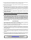
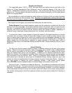
6. Attach the pellet vent adapter (Part # PU-3079) to the exhaust blower with high temperature
silicone and a hose clamp. It is recommended that a “clean out tee” (Part # AC-3067) is installed
between the vent adapter and the five feet (5’) of pellet flex pipe (Part # PU-3060F) or pellet vent
rated flex liner. Route the open end of the flex pipe through the throat of the fireplace or, if
relining the flue with flex liner, drop the liner through the top of the flue and connect. It is
necessary to block off the open area on each side of the flex pipe with metal or flame-retardant
insulation (no paper or combustibles) and if the liner is routed all the way up the flue, the flex liner
should be anchored at the top of the flue as well.
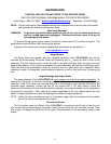
7. The back plate and gasket kit are standard with this unit and are required to cover the fireplace
opening. The cover plate is 32” x 46” and should overlap each side and the top of the fireplace
opening by a minimum of two inches. Refer to the drawing in this manual for the proper method
of installing the cover plate. The adhesive side of the gasket will attach to the rear of the plate
and butt against the firebrick.
8. Once the back plate has been installed, you may carefully slide the entire unit into the fireplace
opening until the plate makes solid contact with the face of the fireplace. You should check to be
sure there is a tight seal around the outside of the cover plate.
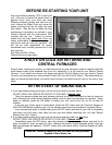
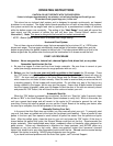
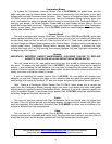
1. If 3” flue pipe exceeds 15’ in length, increase to 4” flue pipe for remaining flue connections.
2. Total flue length should not exceed 35’.
3. Horizontal run not to exceed 4’.
4. Floor protector required depending on hearth size
5. If the total run of outside air connection exceeds 6’, if more than 2 elbows are used, or if a
basement install, use 3” metal pipe (and coupler) instead.
6. Outside Air is mandatory for proper safe operation.
8