


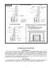
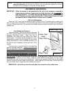
FLUE SYSTEM
Be sure to check local codes in your area.
NOTE
: See the installation drawing later in this manual (Illustration 1).
This unit is equipped with a negative draft system that pulls combustion air through the burn pot
and pushes the exhaust air out of the dwelling. If this unit is connected to the flue system other than
the way explained in this manual, it will not function properly.
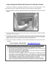
Pellet Vent Pipe
The UL approved pellet vent pipe that we recommend is a twist lock system; however, it is still
recommended that high temperature silicone be used at each joint. England’s Stove Works
recommends the use of Simpson Dura-Vent® twist-lock pipe (if you use other pipe, consult your
local building codes and/or building inspectors, and secure each joint with at least three screws—see
Important Information, above). Do not use “B” vent gas pipe or galvanized pipe with this unit. The
pellet pipe is designed to disassemble for cleaning and should be checked several times during the
burning season — pellet vent pipe is not furnished with the unit and must be purchased separately.
Do not install a flue damper of any kind in this system, and do not connect this unit to a flue
system serving another heating appliance.
Outside Air (Outside Combustion Air Intake)
Outside air is mandatory for this unit to operate properly
. This unit has been designed and tested
with this connection, because so many homes are airtight and there is not adequate combustion air
available inside the dwelling. The air intake pipe is located on the bottom center of the rear of the
unit, and measures 1 ½” inside diameter (I.D.). The connection can be made with a metal 1
7
/
8
” I.D.
coupler and pipe (see “Important Information” section of manual), and should exit through the back
wall of the fireplace (or through a clean out door, if available) that leads directly outside of the
dwelling (external fireplace only). Chimneys which are located on the interior of the structure may
require that outside air intake be routed into the flue, past the damper, and below the exhaust exit
into the chimney itself, or may be run all the way up the chimney alongside the exhaust. Be sure to
secure the pipe to the unit with a clamp or aluminum tape. The outside end of the pipe should be
covered (screened) to prevent foreign matter from entering the system. NOTE: If the total run of the
connection exceeds 6’, or if more than 2 elbows are used, use 3” metal pipe (and coupler) instead.
Note
: If an older unit, measure the opening to determine what size pipe to use or couple to.
FOLLOW ALL APPLICABLE CODES; CODES SUPERCEDE THESE INSTRUCTIONS
Mobile Home Installation
This unit is not approved for mobile home use.
Important Notes Concerning Installation:
IMPORTANT: Improper hook-up (too much pipe, too many elbows, etc.) will cause
the unit not to operate. Call Technical Support (800-245-6489) if you
have questions about your hook-up or if your unit will not operate.
*IMPROPER INSTALLATION: The manufacturer will not be held responsible for damage
caused by the malfunction of a stove due to improper venting
or installation.
Call (800-245-6489) and/or consult a professional installer if you have any questions.
7