


FLUE SYSTEM
Caution: Follow the pipe manufacturer’s installation instructions and directions for
passing through combustible walls and ceilings.
Be sure to check local codes in your area.
NOTE
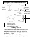
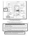
: See the installation drawing later in this manual (Illustration 1).
This unit is equipped with a negative draft system that pulls combustion air through the burn
pot and pushes the exhaust air out of the dwelling. If this unit is connected to the flue system
other than the way explained in this manual, it will not function properly.
For any of these installations, keep in mind that each elbow used reduces draft by 15%; it is
good practice to add 3’ (three feet) of vertical rise for each elbow used. Example: After the 2
nd
elbow used, have 6’ (six feet) of vertical rise before terminating your vent pipe.
Pellet Vent Pipe
The UL approved pellet vent pipe that we recommend is a twist lock system; however, it is
still recommended that high temperature silicone be used at each joint. England’s Stove Works
recommends the use of Simpson Dura-Vent® twist-lock pipe (if you use other pipe, consult
your local building codes and/or building inspectors, and secure each joint with at least three
screws—see Important Information, above). Do not use “B” vent gas pipe or galvanized pipe
with this unit. The pellet pipe is designed to disassemble for cleaning and should be checked
several times during the burning season — pellet vent pipe is not furnished with the unit and
must be purchased separately. Do not install a flue damper of any kind in this system, and
do not connect this unit to a flue system serving another heating appliance.
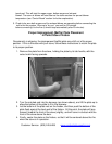
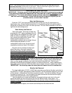
Through the Wall
To vent the unit through the wall, connect the pipe adapter to the exhaust motor adapter. If
the exhaust adapter is at least eighteen inches (18”) above ground level, a straight section of
pellet pipe can be used to initially pass through the wall (see Ill. 1). Your dealer or our factory
should be able to provide you with a kit that will handle most of this installation, which will
include a wall thimble that will allow the proper clearances through a combustible wall. Once
outside the structure, a three-inch (3”) clearance should be maintained to the outside wall and a
clean out tee should be placed on the pipe that extends through the wall. We recommend a
minimum of three feet (3’) of vertical pipe with a 90-degree turn away from the house. At this
point, a one-foot (1’) section and horizontal cap will complete the installation (see Illustration 1).
A wall strap should be placed just below the last 90-degree section to make the system more
stable. If you live in an area that has heavy snowfall, it is recommended the installation be taller
than three feet (3’) to get above the snowdrift line.
The same type installation can be used if your stove is below ground level by adding the
clean-out section and vertical pipe inside until ground level is reached. However, we
recommend basement installation be performed only by a professional installer. For basement
installations, a 3” (three inch) pipe and coupler must be used for Outside Combustion Air, and a
minimum clearance of 3’ (three feet) must be maintained outside the dwelling from the ground to
the Pellet Vent Exhaust Pipe.
The through-the-wall installation is the least expensive and simplest installation. In a
through-the-wall installation you should be mindful of the snowdrift line, as well as dead grass
and leaves. We recommend a three foot (3’) minimum vertical rise on the inside or the outside
of the dwelling. Never terminate the end vent under a deck, in an alcove, under a window or
between two windows. Call (800) 516-3636 to inquire about the AC-3000 Through-the-Wall Kit.