


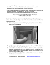
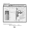
Annual Cleaning
The stove and the flue system should be given a complete cleaning at the end of the
heating season. Remove the burn pot assembly, clean it thoroughly, and re-install it (refer
to Illustration 4); this will require new gasket for the burn pot. Be sure to tighten the set
screws when you replace them, but do not over-tighten. In addition to the cleaning
mentioned for semi-weekly and monthly, the Combustion (exhaust) Blower should be
removed annually and the blower tube vacuumed of any ash build-up. When cleaning or
replacing the blower a new gasket (Part # PU-CBG) should be added between the blower
flange and the steel exhaust tube.
Soot and Fly ash: Formation and Need for Removal – The products of combustion will
contain small particles of fly ash. The fly ash will collect in the exhaust venting system and
restrict the flow of flue gases. Incomplete combustion, such as occurs during startup,
shutdown, or incorrect operation of the room heater will lead to some soot formation which
will collect in the exhaust venting system. The exhaust venting system should be inspected
at least once every year to determine if cleaning is necessary.
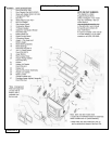
MAINTENANCE
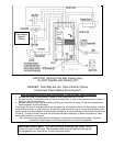
CAUTION: UNPLUG THE UNIT PRIOR TO ANY SERVICE WORK!
SEE EXPLODED DIAGRAM (ILLUSTRATION 4) FOR PARTS REFERENCE
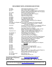
Parts Orders: (800) 516-3636 www.englandsstoveworks.com
Questions: (800) 245-6489
NOTE: Visit our web site for downloadable maintenance sheets and/or a service video that
details and illustrates the following maintenance tasks.
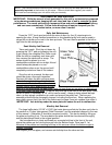
Rear Panel Removal
WARNING: To perform any maintenance inside the rear of the unit, the stove
must be out (no fire), cooled down and unplugged. Electrical shock can occur if the
unit is not unplugged from power.
To remove the rear panel, simply loosen the eight (8) screws (size 5/16”) and flex the
panel. The panel should come off without fully removing the screws.
Instructions for maintenance and part replacement procedures can be found on
www.englandsstoveworks.com
.
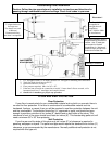
Auger Motors
The Auger Motor and gearbox are one complete assembly (Part #PU-047040), and can
be removed by disconnecting the power leads and loosening the (
5
/
16
” head) set bolt in front
of the assembly. This bolt tightens down on the flat side of the gear shaft and locks the gear
shaft and auger shaft together – once the bolt is loosened, the entire assembly will slide
from the locking collar. There are two motor assemblies on the unit, and both rest on a shelf
when not in operation. When replacing a motor, the assembly should always be placed to
rest on this shelf prior to starting the unit.
Auger Bearings and Auger Shafts
The auger bearings (Part #PU-UCF204-12) are a sealed unit and do not require
lubrication. To replace the Top Auger, all the fuel must be removed from the hopper as well
as from the Top Auger assembly. Once this is done, the four bolts that hold in the bearing
can be removed, followed by the complete auger assembly. Loosen the two (2) set screws
with a 1/8” allen wrench, which will disconnect the bearing from the shaft (the bearing
assembly and auger assembly can be replaced by reversing this procedure). When placing
the auger assemblies in the unit, always tighten the four bolts in a diagonal pattern to ensure
the bearings and shafts are aligned properly.