


Page 24 20248-2-0806
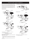
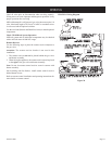
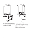
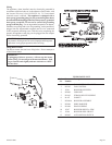
28. Place fan control bracket with wires on top of inner casing.
Remove right, front 10 x 1/2" screw from top of inner casing.
Attach fan control bracket to top of inner casing with 10 x
1/2" screw. Refer to Figure 5 for correct position of fan control
bracket for 10,000 Btu input or 20,000 Btu input.
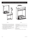
29. Attach inner casing to outer casing with six (6) 10 x 1/2" screws
from Step 6. Tighten two (2) 10 x 1/2" screws at interior, top
of inner casing that were loosened in Step 6.
30. Attach burner assembly to inner bottom with three (3) 10 x
1/2" screws from Step 5.
31. Attach rear log support to inner casing with three (3) 10 x 1/2"
screws from Step 4.
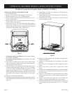
32. Place and align blower diverter on top of inner casing. Attach
deflector to top of inner casing with two (2) 10 x 1/2" screws.
(See Figure 6)
33. Attach top louver with two (2) 8 x 1/2" Phillips screws from
Step 3.
34. Attach screen front.
35. Raise bottom louver.
36. Installation of optional blower assembly is completed.
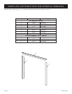
Figure 5 Figure 6
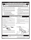
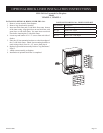
OPTIONAL BLOWER INSTALLATION INSTRUCTIONS (cont.)