


Page 1120248-2-0806
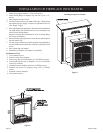
Built-In Fireplace Installation
Built-in installation of this fireplace involves installing fireplace
into a framed-in enclosure. This makes the front of fireplace flush
with wall. If installing a mantel above the fireplace, you must follow
the clearances shown in Figure 5, page 9. Follow the instructions
below to install the fireplace in this manner.
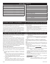
Frame in rough opening. Use dimensions shown in Figure 10 for a
conventional rough opening. Use dimensions shown in Figure 11
for corner rough opening. Be sure to provide gas line for fireplace
and electrical power for VFS-BK optional blower assembly.
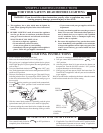
1. Attach two (2) nailing flanges to firebox sides with two (2) 10
x 1/2" screws for each nailing flange.
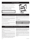
2. Gas line connections must be made at this time. When facing
the appliance the gas supply will enter on right-hand side. See
"Gas Supply" Page 8.
3. Insert fireplace into enclosure.
4. Attach nailing flanges to framing with a screw or nail.
5. Finished wall surface will be flush to the leading edge of fireplace
top and sides.
6. Installation of built-in fireplace is completed.
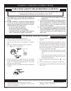
Installation of Trim
1. Lower bottom louver.
2. Remove screen from fireplace.
3. Remove top louver from fireplace [two (2) Phillips screws].
4. Attach right and lift trim to fireplace. Use two (2) Phillips screws
for each side.
5. Attach trim top to fireplace with two (2) Phillips screws.
6. Reattach top louver to fireplace using two (2) Phillips screws.
7. Reattach screen to fireplace.
8. Raise bottom louver.
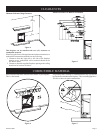
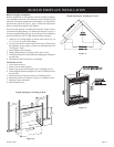
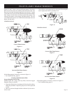
Rough Opening for Installing in Wall
Figure 10
Figure 12
Rough Opening for Installing in Corner
Figure 11
FLUS
H
INSTALLATION
PROJECTE
D
INSTALLATION
1” TO
6
” FRO
M
BACK
25m
m
TO
152m
m
ELECTRICAL
RECEPTACLE
26 3/4”
(680mm)
4” (102mm)
GAS SUPPL
Y
23 1/4” (591mm)
11 1/4”
(286mm)
BUILT-IN FIREPLACE INSTALLATION