


Page 22 20248-2-0806
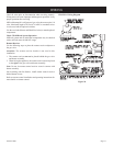
INSTALLING OPTIONAL BLOWER VFS-BK
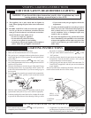
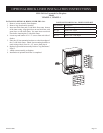
1. Lower bottom louver.
2. Remove screen front by lifting upward on screen front.
3. Remove top louver [(2) 8 x 1/2" Phillips screws].
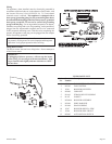
4. Remove rear log support from inner casing [three (3) 10 x 1/2"
screws.] (See Figure 1)
5. Remove three (3) 10 x 1/2" screws that attach burner assembly
to inner bottom. (See Figure 1)
6. Remove six (6) 10 x 1/2" screws that attach inner casing to
outer casing. Loosen two (2) 10 x 1/2" screws at interior, top
of inner casing. Remove inner casing from outer casing by
pivoting left side of inner casing. (See Figure 1)
Figure 1
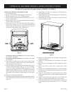
7. For fireplace that is not installed, remove burner assembly
from interior of fireplace.
7. For fireplace that is installed, burner assembly will remain
with fireplace.
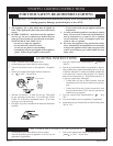
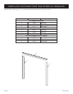
8. Insert blower assembly into left side of outer casing. Motor
with wiring will be to inside of outer casing, blower chute will
be facing upward. (See Figure 2)
9. Place and align two (2) orange motor mounting gaskets at rear
of motor mounting brackets. Start two (2) 8 x 1/2" Phillips
screws into motor mounting brackets and gaskets on side
opposite motor. Start one (1) 8 x 1/2" Phillips screw into top
motor mounting bracket and gasket adjacent to motor. Align
and attach blower assembly to outer casing side. (See Figure
2)
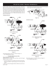
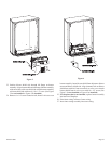
10. Snap Heyco into blower shield side.
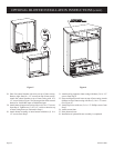
11. Place blower shield side adjacent to motor. Route blower motor
wires through Heyco on blower shield side. (See Figure 3 and
Figure 4)
VFS-BK for Unvented Gas Fireplace Model VF24FP2-1, VF24FP3-1
12. Attach black wire from wire harness to OFF terminal on
AUTO/OFF/ON switch.
13. Attach white/black wire from wire harness to ON terminal on
AUTO/OFF/ON switch.
14. Attach black/red wire from wire harness to AUTO terminal
on AUTO/OFF/ON switch.
Figure 2
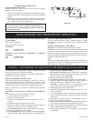
15. Route two (2) flag terminals on wire harness through Heyco
on blower shield side.
16. Attach two (2) flag terminals on wire harness to fan control
(bracket).
17. Route cord set wires through access hole on right side of outer
casing.
18. Insert strain relief in access hole on right side of outer
casing.
19. Attach (1) pin terminal from black (hot) wire, smooth insulation
on cord set to (1) socket terminal from black wire on AUTO/
OFF/ON switch.
20. Attach (1) pin terminal from black (neutral) wire, ribbed
insulation on cord set to (1) socket terminal from black wire
on motor.
21. Attach (1) pin terminal from white wire on AUTO/OFF/ON
switch to (1) socket terminal from white wire on motor.
22. Attach green ground wires from wiring harness and cord set
to interior back of outer casing with one (1) 8 x 1/2" Phillips
screw.
OPTIONAL BLOWER INSTALLATION INSTRUCTIONS