


Page 18 12426-4-0104
GWTB-2 FOR MODELS
GWT-25 (SG, RB), GWT-35 (SG, RB), GWT-50 (SG, RB)
OPTIONAL BLOWER INSTALLATION INSTRUCTIONS
Installing Blower Using Three-Prong Plug
1. Install furnace according to Installation Instructions and Owner's
Manual.
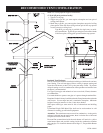
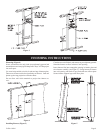
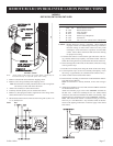
2. Refer to Drawing for measurements to locate (2) mounting holes
on wall surface above furnace.
On Solid Wall
3. After locating mounting holes, attach (2) #10 x 1 1/2" screws provided
in blower kit into wall. Do not completely tighten screwheads to
wall, leave a 7/16" gap between screwheads and wall.
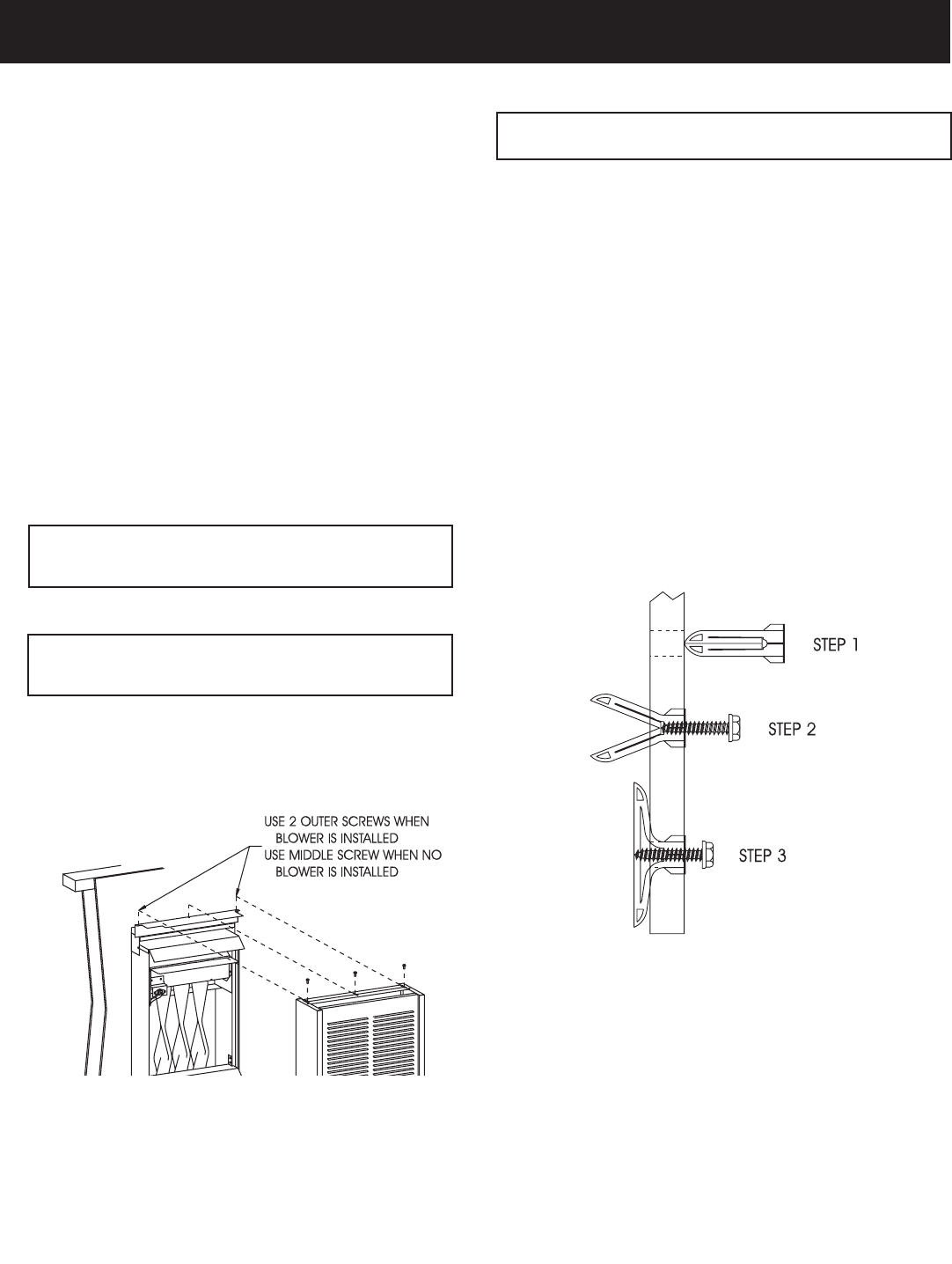
On Sheet Rock Wall
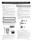
3. After locating mounting holes, drill (2) 5/16" diameter holes into
wall. Insert the (2) plastic expansion anchors into holes. Insert (2)
#10 x 1 1/2" screws provided in blower kit into (2) plastic expansion
anchors. Do not completely tighten screwhead to plastic expansion
anchors, leave a 7/16" gap between screwheads and plastic expansion
anchors. Refer to Figure 2.
4. At the top of outer casing remove (1) screw from center clearance
hole that attaches outer casing to header assembly. Also, remove (2)
screws that attach bottom of outer casing to inner casing.
5. Pull the outer casing forward approximately 1 inch away from wall
surface.
6. Remove (4) 8 x 3/8" screws that attach blower front to blower
housing.
Caution: When removing blower front be careful not to damage
motor coil wires. Damaged coil wires will disable blower
function.
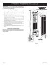
7. Position blower housing on top of header assembly and route three-
prong cord set between left side of outer casing and inner casing.
Caution: Blower cord set routing is important. Cord set should
be in proper location to avoid being overheated. Incorrect routing
of cord set may result in damage to cord set.
8. Replace the outer casing to the wall surface.
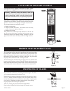
9. Attach outer casing to header assembly. Attention: The center
clearance hole will not be used. The two outside clearance holes
will be used to attach outer casing to header assembly, (1) screw
from Step 4 and (1) screw supplied in hardware package. Refer to
Figure 1.
Figure 1
10. Attach outer casing to inner casing with (2) screws from Step 4.
11. Align key hole slots on back of blower housing with the (2) screws
attached to wall. Position blower housing ß ush with wall surface
and on top of outer casing. Complete tightening blower housing
screws from Step 3 to wall.
12. Attach caps and plugs from blower housing and blower front.
13. Attach blower front to blower housing with (4) 8 x 3/8" screws from
Step 6.
14. Installation of optional blower assembly is completed.
Caution: When installing blower housing onto wall be careful motor
coil is not damaged.
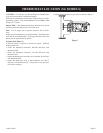
Installing Blower With Hard Wiring
1. When facing the wall opening, install 120V electrical outlet junction
box inside wall opening on left wall stud approximately 12 inches
above header plate.
2. Refer to Drawing for measurements to locate access hole for electrical
wiring on wall surface.
3. After locating access hole, drill a 1/2" hole into wall.
4. Route enough Þ eld wiring from 120V electrical outlet junction box
through 1/2" access hole in wall for connection to blower housing.
5. Install furnace according to Installation Instructions and Owner's
Manual.
6. Refer to Drawing for measurements to locate (2) mounting holes on
wall surface above the furnace.
On Solid Wall
7. After locating mounting holes, attach (2) #10 x 1 1/2" screws provided
in blower kit into wall. Do not completely tighten screwheads to
wall, leave a 7/16" gap between screwheads and wall.
On Sheet Rock Wall
7. After locating mounting holes, drill (2) 5/16" diameter holes into
wall. Insert (2) plastic expansion anchors into holes. Insert (2) #10
x 1 1/2" screws provided in blower kit into (2) plastic expansion
anchors. Do not completely tighten screwhead to plastic expansion
anchors, leave a 7/16" gap between screwheads and plastic expansion
anchors. Refer to Figure 2.
Figure 2
8. Remove three prong cord set from blower housing.
9. Remove (4) 8 x 3/8" screws that attach blower front to blower
housing.
10. Position blower housing on top of header assembly.
11. Route 120V Þ eld wiring into blower housing through cord set hole
on back of blower housing.
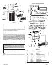
12. Refer to wiring diagram to make wiring connections inside blower
housing. Be sure to follow all local and National electrical codes
when making Þ eld wiring connections.
13. Align key hole slots on back of blower housing with (2) screws
attached to wall. Position blower housing ß ush with wall surface and
on top of outer casing. Complete tightening blower housing screws
from Step 7 to wall.
14. Attach caps and plugs from blower housing and blower front.
15. Attach blower front to blower housing with (4) 8 x 3/8" screws from
Step 9.
16. Installation of optional blower assembly is completed.