


12434-3-0903
Page 9
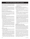
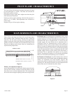
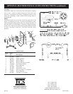
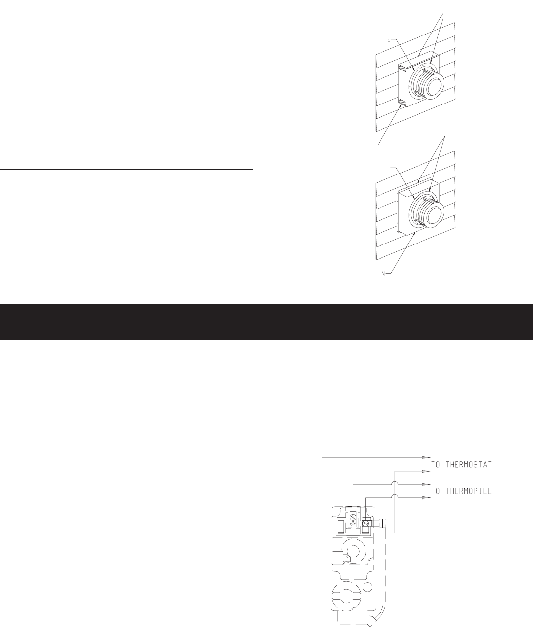
Vinyl siding vent kit, DV-822, is available from Empire
Comfort Systems, Inc. The depth is 3" (76mm), which enables
the vent cap to be extended away from vinyl siding or
projections. The wall depth plus the additional 3" (76mm)
depth of the vinyl siding vent cap extension should not exceed
a total depth of 13" (330mm) for DV-25 and DV-35. (See
Figure 5a)
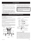
Warning: When vinyl siding vent kit, DV-822 or 2" x 4"
(51mm x 102mm) framing is added to an existing
installation (furnace is installed) do not attempt to add
sections of pipe to the flue outlet tube or air inlet tube. An
air tight seal is required for both tubes. Refer to Parts
List, page 13 to order tubes.
Figure 5a
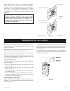
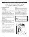
THERMOSTAT LOCATION
Millivolt wall thermostats are specially designed for use on self-
generating systems. They should never be used on line or low
voltage A.C. circuits.
Interior Wall — The thermostat should be installed on an inside
wall away from the furnace but in the same room.
Note: Use 16 gauge wire to prevent excessive loss of millivolts.
Proper operation depends on a good pilot flame. The flame must
cover the top of the thermopile. Cleaning of the pilot orifice and
burner may be required due to spiders.
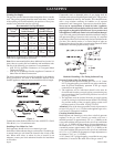
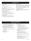
System Check (Figure 6)
A millivolt meter is required to check the system. Millivolt
readings should be:
• Across the thermopile terminals, 400-450 millivolts with
thermostat OFF.
• Across the thermopile terminals, 150-250 millivolts with
thermostat ON.
• Across the thermostat wires at the valve, less than 30 millivolts
with thermostat ON.
• Across the thermostat wires at the thermostat, less than 5
millivolts with thermostat ON. (Strong winds, dirty pilot and
low pressure will reduce readings.)
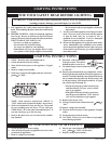
Piezo Pilot Ignitor Instructions
Depressing the red button completely causes a spark to occur at
the pilot. This is a substitute for a match which requires opening
the pilot hole cover.
To light the pilot, it is important that the electrode be 1/8" (3mm)
from the thermopile. The spark must occur at the point the burner
flame hits the thermopile. The end of the electrode will be red hot
with the pilot on.
On a new installation with air in the gas line, it is suggested that
a match be used. The match will light the pilot faster than the
piezo under this condition.
Figure 6
OUTSIDE MOUNTING PLATE
APPLY CAULKING
2 x 4 (51 x 102) FRAMING
Figure 5
APPLY CAULKING
OUTSIDE MOUNTING PLATE
VENT CAP EXTENSION
INCHES (mm)