


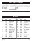
12434-3-0903
Page 7
CLEARANCES
1. In selecting a location for installation, it is necessary to provide
adequate accessibility clearances for servicing and proper
installation.
2. Unit is supported by a wall bracket secured to the wall.
3. The minimum clearances from casing to combustible
construction is 48" (121cm) on top, 6" (152mm) on each side
and 4" (102mm) from the floor or from the top surface of
carpeting, tile or other floor covering and 0" (0mm) to rear
wall.
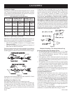
4. The minimum distance from the center of the vent cap to the
nearest outside corner or obstruction is 24" (610mm).
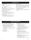
5. The DV-25 and DV-35 minimum wall depth is 4 1/2"
(114mm) (and the maximum is 13" (330mm). The use of
tubes not supplied by the manufacturer results in
unsatisfactory performance.
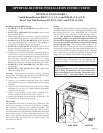
The vent terminal of a direct vent appliance, with an input of
50,000 (14.6 KW) BTU per hour or less shall be located at least
9" (229mm)from any opening through which flue gases could
enter a building. The bottom of the vent terminal and the air
intake shall be located at least 12" (305mm) above grade.
WARNING: The nearest point of the vent cap should be
a minimum horizontal distant of six (6) (1.83m) feet from
any pressure regulator. In case of regulator malfunction,
the six (6) (1.83m) feet distance will reduce the chance of
gas entering the vent cap.
INSTALLATION INSTRUCTIONS
Location of Furnace
Pick a location on an outside wall with a clear space of 28"
(711mm) high by 49" (124cm) wide in the room.
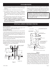
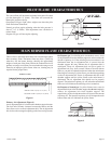
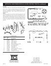
Locating Wall Opening
The furnace is to be located on an outside wall. Locate wall studs
so that wall opening will be located between wall studs. The wall
studs can be used for attachment of wall mounting bracket. The
wall opening required as shown in Figure 3 is a diameter of 7 1/2
inches (191mm).
A template is provided in furnace carton for positioning furnace on
the wall. Also, refer to Figure 3 for positioning the furnace on wall
and for locating gas line connection.
Figure 3 will position the furnace four inches (102mm) off the
floor. If it is desired to position the furnace higher on the wall, add
the difference to the "A," "B" and "C" dimensions. Note: the vent
opening is not in the center of the furnace.
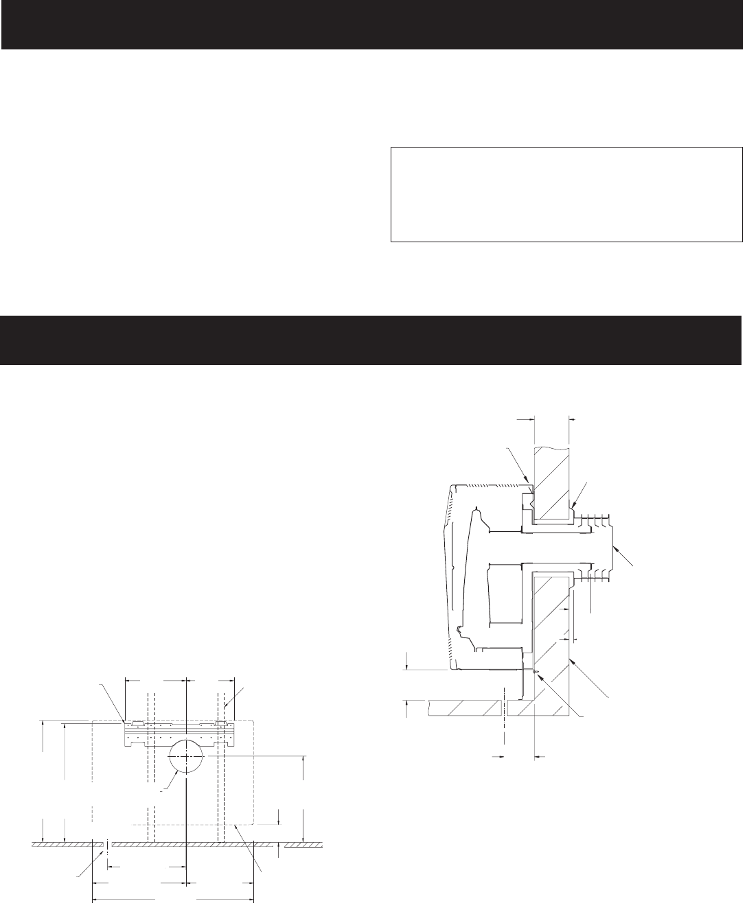
Figure 3
Figure 4
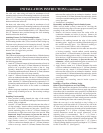
Installing Wall Mounting Bracket
Locate and cut wall opening. If there is insulation above the wall
opening (air inlet tube) a barrier should be installed above the wall
opening (air inlet tube) to prevent insulation from coming in
contact with the air inlet tube. The barrier must not penetrate into
the 7 1/2" (191mm) diameter wall opening. Place the flat surface
of the wall mounting bracket toward the wall. Insert half round
flange of wall mounting bracket into and at the top of the wall
opening. The half round flange of the wall mounting bracket must
be in contact with the sheetrock or wood at the top of the wall
opening. Level the wall mounting bracket in the wall opening.
37
(940)
C
19 3/4
(502)
WALL MOUNTING
BRACKET
A
28
(711)
B
27 3/16
(691)
7 1/2 (191) DIA.
WALL OPENING
GAS INLET
TO VALVE
OUTER CASING
OF UNIT
15 1/2
(394)
11
(279)
14
(356)
2 x 4 ((51 x 102) STUDS
16 (406) ON CENTER
21 1/2
(546)
17 3/4
(451)
4 (102) MIN.
INCHES (mm)
4 1/2 (114) MIN. WALL DV-25, DV-35
13 (330) MAX. WALL DV-25, DV-35
INCHES (mm)
(DV-25-2 SHOWN)
UNIT IS SUPPORTED
BY WALL BRACKET
4 (102) MIN.
MOUNTING PLATE
(CAULK UNDER FLANGE)
VENT CAP
FLUE OUTLET TUBE EXTENDS
2 1/2 (64) BEYOND WALL
AIR INLET TUBE EXTENDS
1/2 (13) BEYOND WALL
OUTSIDE WALL
UNIT FASTENED TO WALL
WITH (2) SCREWS
4
(102)
GAS INLET TO REAR OF CASING