


12434-3-0903Page 8
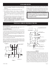
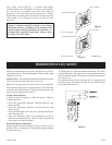
On solid wall, when using wall studs for attachment of wall
mounting bracket, fasten wall mounting bracket to wall studs with
(2) #10 x 1 1/2" (38mm) screws provided and fasten (2) additional
#10 x 1 1/2" (38mm) screws provided through the wall mounting
bracket and into the solid wall.
On sheet rock, when using wall studs for attachment of wall
mounting bracket, fasten wall mounting bracket to wall studs with
(2) #10 x 1 1/2" (38mm) screws provided and by using wall
opening for access, fasten 2 additional #10 x 1 1/2" (38mm) screws
and (2) Tinnerman nuts provided through the wall mounting
bracket and into the sheet rock.
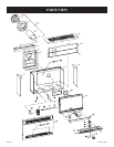
Attaching Furnace To Wall Mounting Bracket
Hang furnace on wall mounting bracket by aligning (2) tabs on
wall mounting bracket with (2) slots located on inner casing top.
The inner casing bottom is to be fastened to the wall. On solid
wall, fasten inner casing bottom with (2) #10 x 1 1/2" (38mm)
screws provided. On sheet rock wall, fasten inner casing
bottom with (2) toggle bolts provided.
Cutting Vent Tubes
This is the most important part of the installation. With the furnace
installed on wall the 6" (152mm) diameter air inlet tube and the 4"
(102mm) diameter flue outlet tube are to be marked and cut using
the following procedure.
1. Attach 6" (152mm) diameter air inlet tube onto the collar of air
drop assembly. Be sure 6" (152mm) diameter air inlet tube is
placed as far as possible onto the collar of the air drop
assembly. Mark the 6" (152mm) diameter air inlet tube 1/2"
(13mm) beyond the outside wall. Remove 6" (152mm) diameter
air inlet tube from collar of air drop assembly.
2. Attach 4" (102mm) diameter flue outlet tube onto flue outlet
collar on combustion chamber. Be sure 4" (102mm) diameter
flue outlet tube is placed as far as possible onto the collar of flue
outlet. Mark the 4" (102mm) diameter flue outlet tube 2 1/2"
(64mm) beyond the outside wall. Remove 4" (102mm) diameter
flue outlet tube from collar of flue outlet on combustion
chamber.
3. Mark or wrap tape completely around the tubes at the marked
points to help in making a true cut. Do not crimp or enlarge
tubes.
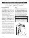
Installing Vent Assembly
1. Place provided caulking beneath the edge of the outside
mounting plate. Use additional caulking to correct uneven wall
surface, such as clapboard.
2. Attach 6" (152mm) diameter air inlet tube onto the collar of
air drop assembly. Attach caulked, outside mounting plate
into the 6" (152mm) diameter air inlet tube. Position the
outside mounting plate so that 6" (152mm) diameter air
inlet tube has a slight downward slope to the outside. The
downward slope is necessary to prevent the entry of
rainwater. Attach outside mounting plate to exterior wall
with (4) #10 x 1 1/2" (38mm)screws provided.
3. Apply furnace cement to 4" (102mm) diameter flue outlet
collar on combustion chamber and to 4" (102mm) diameter
collar on vent cap. Attach 4" (102mm) diameter flue outlet
INSTALLATION INSTRUCTIONS (continued)
tube onto flue outlet collar on combustion chamber. Attach
vent cap into the 4"(102mm) diameter flue outlet tube. Attach
vent cap to outside mounting plate with (3) #10 x 1/2" (13mm)
screws provided.
4. Installation is completed.
Reassembly And Resealing Vent-Air Intake System
When vent-air intake system is removed for servicing the
furnace, the following steps will assure proper reassembly and
resealing of the vent-air intake assembly.
1. Remove old furnace cement from flue outlet collar on
combustion chamber and collar of vent cap. Remove old
furnace cement from both ends of 4" (102mm) diameter flue
outlet tube.
2. Remove old caulking beneath the edge of the outside
mounting plate. Apply new caulking beneath the edge of
the outside mounting plate. Use additional caulking to
correct uneven wall surface, such as clapboard.
3. Attach 6" (152mm) diameter air inlet tube onto the collar
of air drop assembly. Attach caulked, outside mounting
plate into the 6" (152mm) diameter air inlet tube. Position
the outside mounting plate so that 6" (152mm) diameter air
inlet tube has a slight downward slope to the outside. The
downward slope is necessary to prevent the entry of
rainwater. Attach outside mounting plate to exterior wall
with (4) #10 x 1 1/2" (38mm) screws provided.
4. Apply furnace cement to 4" (102mm) diameter flue outlet
collar on combustion chamber and to 4" (102mm) diameter
collar on vent cap. Attach 4" (102mm) diameter flue outlet
tube onto flue outlet collar on combustion chamber. Attach
vent cap into the 4" (102mm) diameter flue outlet tube. Attach
vent cap to outside mounting plate with (3) #10 x 1/2" (13mm)
screws provided.
5. Reassembly and resealing vent-air intake system is
completed.
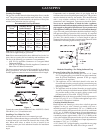
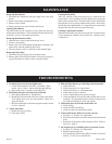
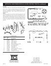
Installing a Vent Near a Window Ledge,
Other Type of Projection or on Vinyl Siding
Direct vent furnaces are designed to be installed on a uniform
outside wall. When the wind comes from any angle (up, down or
from either side), it must hit the vent cap equally over both the air
inlet and the flue outlet portions of the vent. Any wall projection,
such as a door or window casing, which disturbs the wind on one
side of the air inlet section will result in back pressure on the flue
section smothering the flame and eventual pilot outage.
When the vent cap is to be installed on vinyl siding or it
appears that a projection within 6" (152mm) of any side of the
air inlet section could shield the air inlet section, the entire
vent should be supported away from the wall at least the distance
of the projection. 2" x 4" (51mm x 102mm) framing whose
outside dimensions match the overall dimensions of the
mounting plate is recommended. The 2" x 4" (51mm x
102mm) framing protects vinyl siding from possible warpage
or discoloration. All joints can then be sealed and painted. The
wall depth plus the additional depth of the 2" x 4" (51mm x
102mm) framing should not exceed a total depth of 13" (330mm)
for DV-25 and DV-35. (See Figure 5)