


13119-6-0107 Page 9
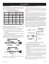
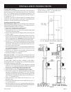
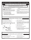
Locating Wall Opening
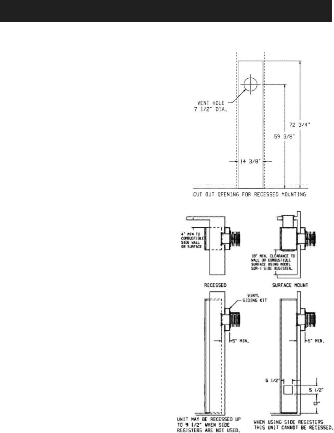
The furnace is to be located on an outside wall. Locate wall studs so
that wall opening will be located between wall studs. The furnace
is 14 1/8” in width and can be recessed between standard 16” on
center wall studs. The wall opening required as shown in Figure 5
is a diameter of 7 1/2”.
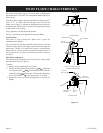
A template is provided in furnace carton for positioning furnace
on the wall. Also, refer to Figure 5 and Figure 7 for positioning the
furnace on wall and for locating gas line connection.
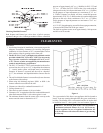
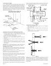
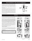
Installing Optional Side Outlets
Side outlet register, SOR-1 may be installed on one or both sides
of the furnace at the required clearances of 18” to adjacent wall or
combustible material as shown in Figure 6.
1. Turn “OFF” all electric power to the furnace.
2. Remove the front panel from the furnace.
3. Remove the two (2) 8 x 3/8” screws that attach the inner shield
cover plate to the inner shield.
4. Scribe a line between the four dimples on the outer casing side
to form a square.
5. Drill a pilot hole within the scribed square on the outer casing.
Remove the sheet metal within the scribed square with a tin
snips or comparable tool.
Attention! Do not cut the electrical
wires located between the outer casing and the inner shield.
6. Insert the 5” x 5” inner boot through the outer casing. Align the
clearance holes on the inner boot with the screw holes on the
inner shield. Attach inner boot to inner shield with two (2) 8 x
3/8” screws removed in Step 3.
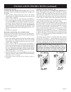
7. Place the register over the 5 1/2” square opening with the louvers
set for the desired direction and mark the mounting holes using
the register as a template.
8. Drill two (2) 1/8” diameter holes in cabinet side and attach the
register with two (2) 10 x 1” provided screws.
9. Installation of SOR-1 is completed.
Side outlet kit, SOK-1, 10” boot assembly with register, for warm
air discharge into an adjoining room may be installed on either side
of the furnace at the required clearance of 4” to adjacent wall as
shown in Figure 6.
To install SOK-1, please use Steps 1 through 5 in the SOR-1
instructions for DVC-35T furnaces. Now, use the following Steps
to complete installation of the SOK-1.
1. Using the inner and outer boots as hole templates, mark and
drill four (4) 1/8” (3mm) diameter holes in the inner shield and
four (4) 1/8” (3mm) diameter holes in the cabinet side.
2. Locate and cut a 6 3/4” square opening through wall.
3. Attach furnace to wall (see Attaching Furnace to Wall
).
4. With furnace in place, after checking alignment of side outlet
opening in wall and furnace, place the 9 3/8” x 9 3/8” side outlet
wall plate over outer boot, pass the outer boot through the wall
and attach side wall plate to furnace side of wall with two (2)
10 x 1 1/2” provided screws.
5. Attach outer boot to the cabinet side with four (4) 8 x 1/4”
provided screws.
6. Position and attach inner boot to inner shield with four (4) 8 x
1/4” provided screws.
7. Place the register over the 6 3/4” square opening with the lou
-
vers positioned for the desired discharge direction and mark the
mounting holes using the register as a template.
Figure 5
Figure 6
8. Drill two (2) 1/8” diameter holes in the wall and attach the
register with two (2) 10 x 1 1/2” provided screws.
9. Installation of SOK-1 is completed.
INSTALLATION INSTRUCTIONS