


13119-6-0107 Page 11
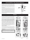
Installing a Vent Near a Window Ledge,
Other Type of Projection or on Siding (vinyl, aluminum, etc.)
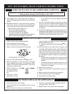
Direct vent furnaces are designed to be installed on a uniform
outside wall. When the wind comes from any angle (up, down or
from either side), it must hit the vent cap equally over both the air
inlet and the flue outlet portions of the vent. Any wall projection,
such as a door or window casing, which disturbs the wind on one
side of the air inlet section will result in back pressure on the flue
section smothering the flame and eventual pilot outage.
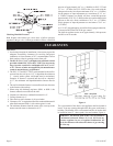
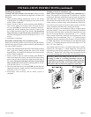
When the vent cap is to be installed on siding or it appears that a
projection within 6” of any side of the air inlet section could shield
the air inlet section, the entire vent should be supported away from
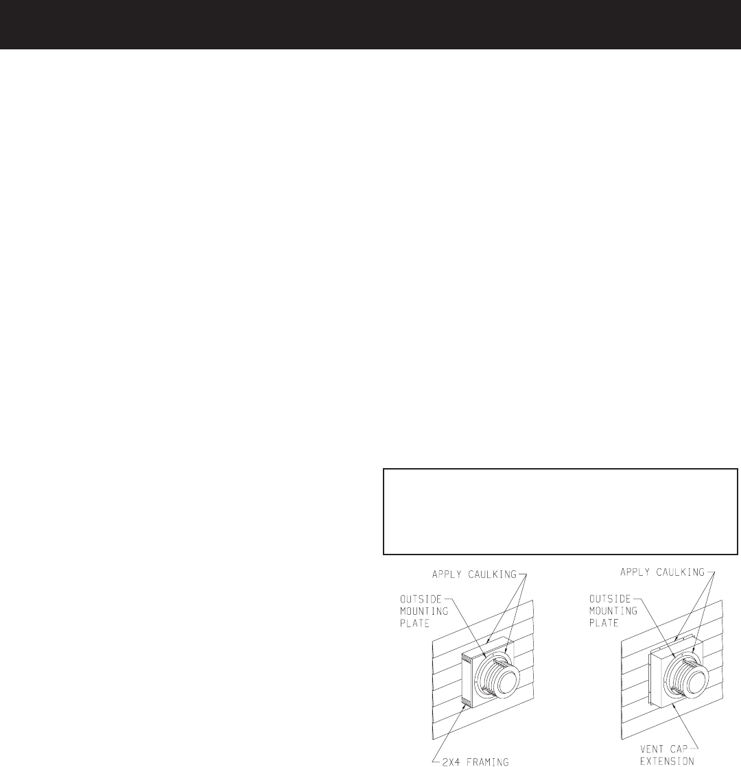
the wall at least the distance of the projection. 2” x 4” framing
whose outside dimensions match the overall dimensions of the
mounting plate is recommended. The 2” x 4” framing protects
siding from possible warpage or discoloration. All joints can then
be sealed and painted. The wall depth plus the additional depth
of the 2” x 4” framing should not exceed a total depth of 14” for
DVC-35T. (See Figure 10)
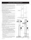
Vinyl siding vent kit, DV-822, is available from Empire Comfort
Systems, Inc. The depth is 3”, which enables the vent cap to be
extended away from siding or projections. The wall depth plus the
additional 3” depth of the vinyl siding vent cap extension should
not exceed a total depth of 19” for DVC-35T. (See Figure 11)
Warning: When vinyl siding vent kit, DV-822 or 2” x 4”
framing is added to an existing installation (furnace is
installed) do not attempt to add sections of pipe to the flue
outlet tube or air inlet tube. An air tight seal is required for
both tubes. Refer to Parts List, page 16 to order tubes.
Figure 10 Figure 11
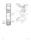
Installing Vent Assembly
Attention: DO NOT attempt to cut vent tubes. When you order
appropriate vent kit for measured wall depth the vent tubes will
fit together.
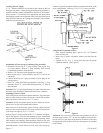
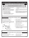
1. Place provided caulking beneath the collar of the outside
mounting plate. Use additional caulking to correct uneven wall
surface, such as clapboard.
2. Insert six inch air tube on outside mounting plate INTO six
inch air tube attached to air drop. Place four inch flue tube
on vent cap OVER four inch flue tube attached to outlet box.
Position the outside mounting plate so that six inch air tube
has a slight downward slope to the outside. The downward
slope is necessary to prevent the entry of rainwater. Attach
outside mounting plate to exterior wall with four (4) 10 x 1 1/2”
screws.
3. Installation is completed.
Reassembly And Resealing Vent-Air Intake System
When vent-air intake system is removed for servicing the furnace,
the following steps will assure proper reassembly and resealing of
the vent-air intake assembly.
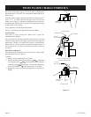
1. Remove old caulking beneath the collar of the outside mounting
plate. Apply new caulking beneath the collar of the outside
mounting plate. Use additional caulking to correct uneven wall
surface, such as clapboard.
2. Insert six inch air tube on outside mounting plate INTO six
inch air tube attached to air drop. Position the outside mounting
plate so that six inch air tube has a slight downward slope to
the outside. The downward slope is necessary to prevent the
entry of rainwater. Attach outside mounting plate to exterior
wall with four (4) 10 x 1 1/2” screws.
3. Place four inch flue tube on vent cap OVER four inch flue tube
attached to outlet box. Attach vent cap to outside mounting plate
with three (3) 10 x 1/2” screws.
4. Reassembly and resealing vent-air intake system is
completed.
INSTALLATION INSTRUCTIONS (continued)