


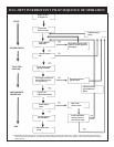
Page 14 13119-6-0107
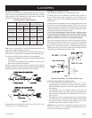
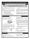
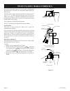
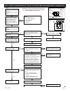
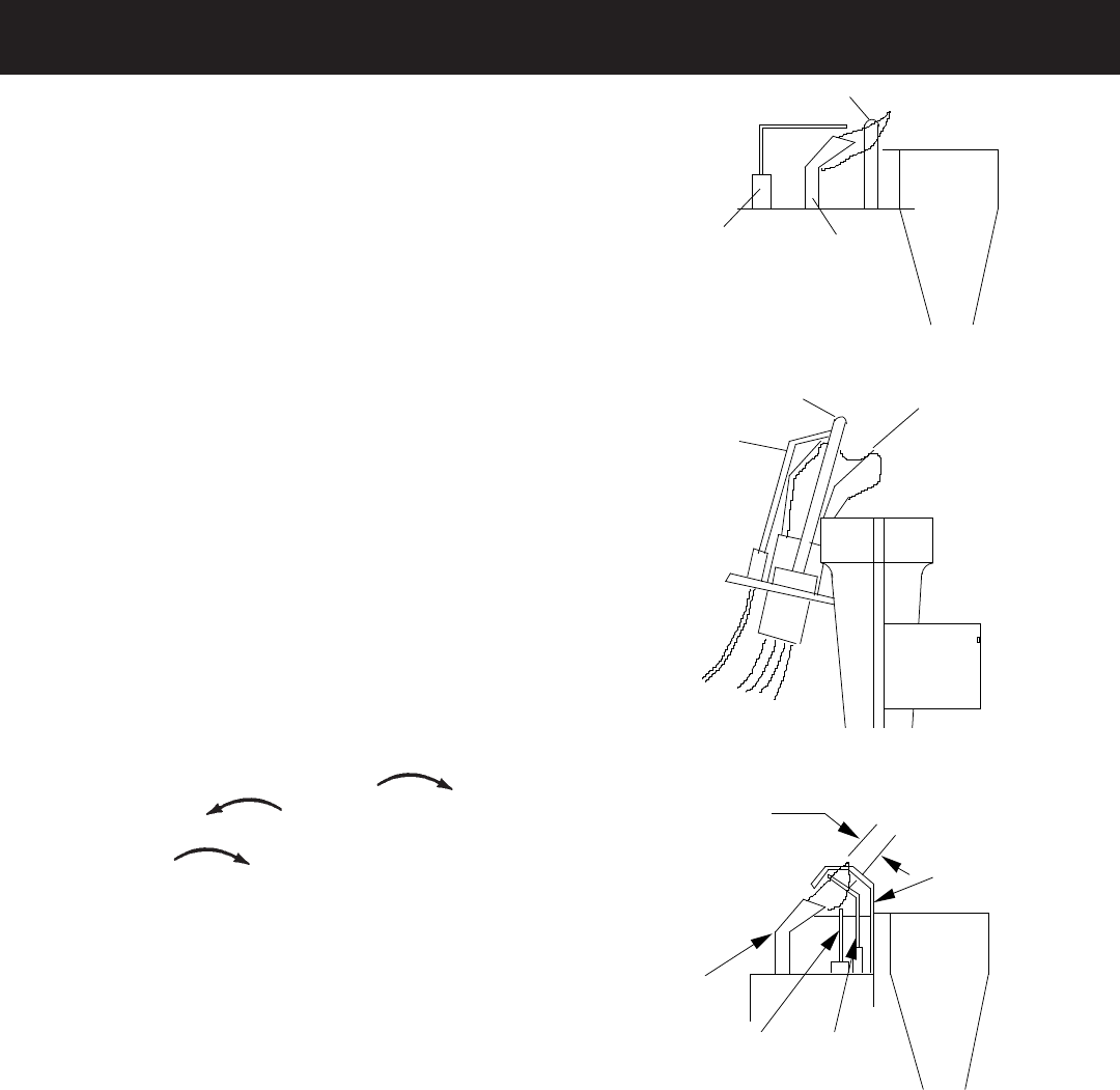
The correct pilot flame (Figure 12) will be blue, extending past
the thermocouple. The flame will surround the thermocouple just
below the tip.
Natural gas pilots require adjusting when the inlet gas pressure is
above 5” w.c. (1.245kPa). Remove the pilot cover screw on the
control valve (Figure 3), and turn the adjustment screw clockwise
to reduce flame. Replace pilot cover screw to eliminate gas leaking
at that control valve opening.
LP gas (propane) will not require adjustment.
After use, cleaning may be required for the proper flame.
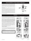
IP-Model Pilot
This heater is using a Honeywell “Smart Valve” system for
intermittent pilot ignition.
On a call for heat by the thermostat this control turns on a 24 volt
mini hot surface ignitor which lights a pilot that in turn lights the
main burner. The gas valve used in this system is a step opening
which opens at a lower pressure for ignition and then steps to a
full inlet pressure of 4” pressure on Natural gas and 10” pressure
on LP gas.
Pilot Flame Adjustment
The pilot flame should envelop 3/8 to 1/2 inch (10 to 13mm) of the
tip of the flame rod. See Figure 12.
To adjust:
1. Remove the pilot adjustment cover screw.
2. Turn the inner adjustment screw clockwise
to decrease
or counterclockwise to increase pilot flame. Pilot ad-
justment is shipped at full flow rate. Turn the inner adjustment
screw clockwise if the inlet pressure is too high.
3. Replace the cover screw after the adjustment to prevent gas
leakage.
SPARK�
ELECTRODE
THERMOCOUPLE
PILOT
BURNER
STANDING PILOT
PILOT LOCATION END VIEW
PILOT SHIELD
THERMOCOUPLE
SPARK�
ELECTRODE
STANDING PILOT SHOWN
BURNER
PILOT
HOT SURFACE�
IGNITOR
FLAME�
ROD
GROUND�
ELECTRODE
3/8" TO 1/2"�
PILOT FLAME
IP-MODEL PILOT
Figure 12
PILOT FLAME CHARACTERISTICS