


Page 10 13119-6-0107
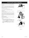
Locating Electric Supply
A 7/8” diameter knockout is provided at the bottom of the left
and right side panels. A three-prong (grounding) plug assembly is
located within the control compartment (bottom) of the furnace.
Please remove 7/8” knockout from appropriate side panel when
routing plug assembly to an electrical outlet. Unit can be hard wired
when recessed. Remove the 3 prong plug assembly and terminate
inside the unit junction box.
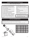
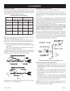
Figure 7
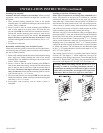
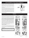
Installation of Three-prong (Grounding) Plug Assembly
1. Disconnect nylon cap on 3’ plug assembly from nylon plug
on wiring harness. Remove 3’ plug assembly from control
compartment (bottom) of the furnace.
2. Remove 7/8” knockout from appropriate side panel.
3. Insert nylon cap on 3’ plug assembly into the 7/8” hole in the
side panel.
4. Connect nylon cap on 3’ plug assembly to nylon plug on the
wiring harness.
5. Place 7/8” strain relief bushing around the cord of the 3’ plug
assembly. Insert 7/8” strain relief bushing into the 7/8” hole in
the side panel.
Attention! The 7/8” strain relief bushing is located within the same
envelope as the Installation Instructions and Owner’s Manual.
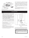
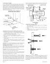
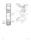
Attaching Furnace to Wall
Place collar on four inch flue tube against outlet box. Align clearance
holes on collar with screw holes in outlet box. Attach four inch flue
tube to outlet box with four (4) 10 x 1/2” screws.
Attention: Do not overtighten screws because outlet box must be
able to move as flue tube expands and contracts.
Place collar on six inch air tube against air drop. Align clearance
holes on collar with screw holes in air drop. Attach six inch air tube
to air drop with eight (8) 10 x 1/2” screws.
Refer to Figure 5 for the location of the 7 1/2” diameter wall open
-
ing for the furnace. After the wall opening has been located and
cut, position flue outlet on furnace in center of wall opening. Insert
tubes through wall opening. When attaching furnace to the wall
remove that portion of baseboard and molding on the wall which is
behind the furnace. Attach furnace to wall, at the outer casing top,
with two (2) plastic expansion anchors provided and to floor, at the
outer casing bottom, with two (2) 10 x 1 1/2” screws provided.
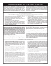
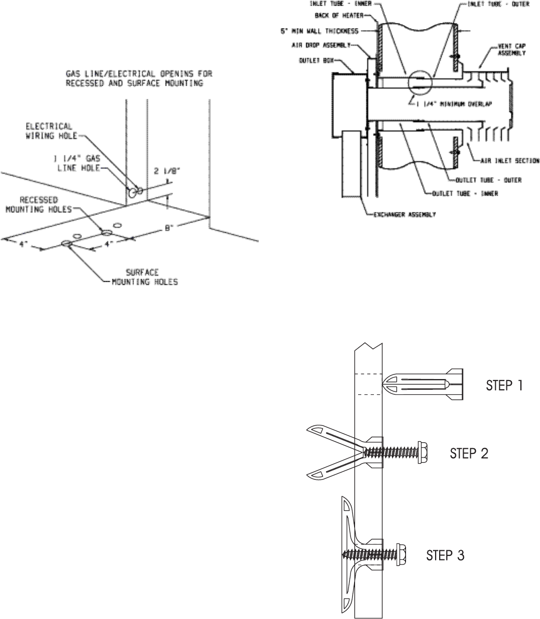
Figure 8
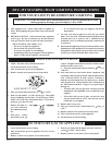
Using Plastic Expansion Anchors
1. After locating mounting holes, drill two (2) 5/16” diameter
holes into the wall.
2. Insert two (2) plastic expansion anchors provided into the
holes.
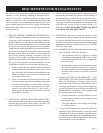
3. Tighten two (2) 10 x 1” screws provided into the plastic
expansion anchors. (See Figure 9)
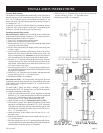
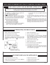
Figure 9
Attention! The screw holes on the outer casing bottom are off-set
the floor approximately 3/8”. Do not over-tighten screws and dis-
tort the off-set on the outer casing bottom. Distortion of the outer
casing bottom will not allow the lower front panel to be attached
to the furnace.