


Page 6 13119-6-0107
Introduction
Always consult your local Building Department regarding regulations,
codes or ordinances which apply to the installation of a direct vent wall
furnace.
Instructions to Installer
1. Installer must leave instruction manual with owner after
installation.
2. Installer must have owner fill out and mail warranty card supplied
with furnace.
3. Installer should show owner how to start and operate furnace and
thermostat.
Warning:
Any change to this furnace or its control can be dangerous. This
is a heating appliance and any panel, door or guard removed for
servicing an appliance must be replaced prior to operating the
appliance.
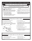
General Information
This furnace is design certified in accordance with American National
Standard/CSA Standard Z21.86 and CSA 2.32 by the Canadian Standards
Association, as a fan type direct vent wall furnace to be installed according
to these instructions.
Any alteration of the original design, installed other than as shown in
these instructions or use with a type of gas not shown on the rating plate
is the responsibility of the person and company making the change.
Important
All correspondence should refer to complete Model No., Serial No. and
type of gas.
Notice: During initial firing of this unit, its paint will bake out and smoke
will occur. To prevent triggering of smoke alarms, ventilate the room in
which the unit is installed.
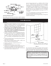
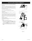
Installation on Rugs and Tile
If this appliance is installed directly on carpeting, tile or other combustible
material other than wood flooring the appliance shall be installed on a metal
or wood panel extending the full width and depth of the appliance.
The base referred to above does not mean the fire-proof base as used on
wood stoves. The protection is for rugs that are extremely thick and light
colored tile.
Installation in Residential Garages
Gas utilization equipment in residential garages shall be installed so that
all burners and burner ignition devices are located not less than 18” above
the floor.
Such equipment shall be located, or protected, so it is not subject to physical
damage by a moving vehicle.
Qualified Installing Agency
Installation and replacement of gas piping, gas utilization equipment or
accessories and repair and servicing of equipment shall be performed
only by a qualified agency. The term “qualified agency” means any
individual, firm, corporation or company which either in person or through
a representative is engaged in and is responsible for (a) the installation
or replacement of gas piping or (b) the connection, installation, repair or
servicing of equipment, who is experienced in such work, familiar with
all precautions required and has complied with all the requirements of the
authority having jurisdiction.
State of Massachusetts: The installation must be made by a licensed
plumber or gas fitter in the Commonwealth of Massachusetts.
The installation must conform with local codes or, in the absence of local
codes, with the National Fuel Gas Code ANSI Z223.1/NFPA 54* Natural
Gas and Propane Installation Code, CSA B149.1.
*Available from the American National Standards Institute, Inc., 11 West
42nd St., New York, N.Y. 10036.
High Altitudes
For altitudes/elevations above 2,000 feet, input ratings should be reduced
at the rate of 4 percent for each 1,000 feet above sea level. For Canadian
high altitude applications, this appliance is suitable for installation at
elevations between 0 feet and 4,500 feet without change.
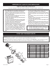
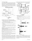
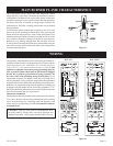
Piezo Pilot Ignitor Instructions
Depressing the red button completely causes a spark to occur at the pilot. This
is a substitute for a match which requires opening the pilot hole cover.
To light the pilot, it is important that the electrode be 1/8” from the
thermocouple. The spark must occur at the point the burner flame hits the
thermocouple. The end of the electrode will be red hot with the pilot on.
On a new installation with air in the gas line, it is suggested that a match
be used. The match will light the pilot faster than the piezo under this
condition.
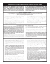
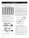
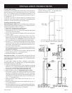
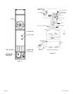
Model DVC-35T DVC-35IPT
Input BTU/HR 35,000 35,000
Height 72 1/2” 72 1/2”
Width
14 1/8” 14 1/8”
Depth 10 3/8” 10 3/8”
Gas Inlet 1/2” Pipe 1/2” Pipe
CFM 275 275
Accessories
SOR-1 Register, Side Outlet
SOK-1 Side Outlet Kit, 10” (25.4cm) Boot Assembly with Register
*DV-822 Vinyl Siding Vent Kit
* DV-822, Vinyl siding vent kit, adds 3” to wall depth. You must include the three (3) additional inches for TOTAL
wall depth when ordering a
vent kit.
INTRODUCTION
SPECIFICATIONS