


www.enviromaster.com
9
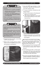
Multi-zone Heat Pump Condensing Units
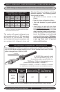
The system will support refrigerant runs
to the inside unit of up to 100' equivalent
feet with a 35' rise included. The units
are furnished with sweat connections and
are equipped with refrigerant valves and
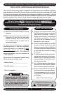
MultI-zonE HEAt PuMP rEfrIgErAnt PIPIng InStAllAtIon
Schrader ttings for charging and taking
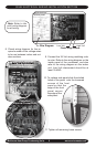
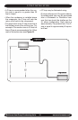
pressure readings. The following precau-
tions should be made:
• Be certain no burrs remain on the
ttings.
• Use only clean refrigeration tubing.
• Use tube benders to guard against
kinking.
• Avoid piping on wet and rainy days
and insulate suction line. Be certain
that plastic end caps remain in place
when inserting through wall openings.
Isolate tubing from transmitting vibra-
tion to the building or unit and avoid
contact with sharp edges. Refrigera-
tion valves should be wrapped with
a wet rag "heat sink" to protect
valves while brazing.
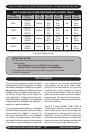
INTERCONNECTING TUBING SPECS
S2HB, T2HB, T3HB, & T4HB models:
Nominal
Circuit
Capacity
Maximum
Length
Maximum
Lift
Liquid
Line
OD
Suction
Line
OD
9,000 100’ 35’ 1/4” 1/2”
12,000 100’ 35’ 1/4” 1/2”
18,000 100’ 35’ 3/8” 5/8”*
24,000 100’ 35’ 3/8” 3/4”
NOTE: Refrigerant Piping Installation for all of the multi-zone heat pump models.
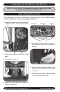
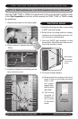
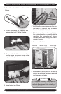
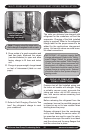
PISTON/ORIFICE CHANGE KIT INSTALLATION
Air Handler
When a WLH24 or UNH24 air handler is matched with a T2HB or T3HB contain-
ing a 24,000 Btuh nominal capacity circuit, the air handler must have it’s stock
piston changed from 0.059 to 0.063.
A 24,000 Btuh nominal circuit
can be identied by the “4” in
the model number capacity eld (i.e.
T2HBx4xx). Refer to the instructions sup-
plied with kit part number; 240006777.
Model #
Air Handler
Condenser
Btuh
Factory Installed
Piston/Orice Size
Field Changeover
Piston/Orice Size
WLH24
or
UNH24
T2HB2400
T2HB8400
T2HB4400
T3HB9940
T3HB9240
T3HB2240
.059” .063”
Note: This kit is only supplied with the above Heat Pump models.
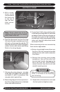
* CAH24, UNH24, WLH24 Suction Connection size
is 3/4” O.D. and must bush down to 5/8” for 18,000
Btuh circuits at the indoor unit.
Circuit Designators: 9 = 9000 Btuh • 2 = 12000 Btuh • 8 = 18000 Btuh • 4 = 24000 Btuh
(ex. - 8400 consists of one 18000 Btuh compressor and one 24000 Btuh compressor)