


www.enviromaster.com
7
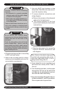
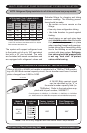
Multi-zone Heat Pump Condensing Units
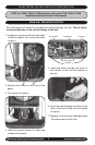
t2HB, t3HB, And t4HB InStAllAtIon InStructIonS SEctIon
NOTE: For S2HB installation refer to the S2HB Installation Instruction in this manual.
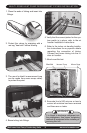
1. Remove the screw on the back panel.
2. Remove panel to expose eletrical
wiring.
3. Location of electrical and tubing connec-
tions on back of unit.
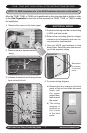
ELECTRICAL WIRING
1. All electrical wiring must be run according
to NEC and local codes.
2. Refer to the unit rating plate for voltage,
minimum circuit ampacity and over cur-
rent protection requirements.
3. Use only HACR type breakers or time
delay fuses. Select the wire size accord-
ing to the ampacity rating.
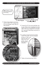
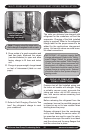
Remove the
four screws
on the front
panel
4. To access wiring diagram:
a) Remove the four screws on the front
panel of the unit and slide the panel
down until
the upper
edge is free,
then remove
the panel.
b) The wiring
diagram is
located on
the inside
of the front
panel.
Wiring
Diagram
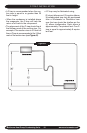
After the T2HB, T3HB, or T4HB unit is positioned on the concrete slab or platform (refer
to the Site Preparation in the front of this manual) the T2HB, T3HB, or T4HB is ready
for installation:
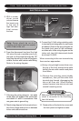
Common
Suction
Pressure
Access
Point
High
Pressure
Reset
(18 & 24)
Vapor
(Suction)
Liquid
High Volt
Low Volt
Mounting
Screw