


www.enviromaster.com
8
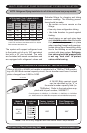
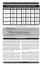
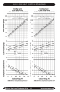
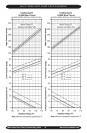
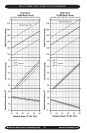
Multi-zone Heat Pump Condensing Units
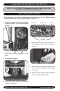
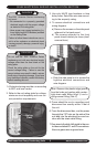
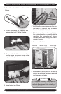
5. With a screw-
driver punch
out and remove
the knock-outs
in the low &
high Volt elec-
trical connec-
tion box.
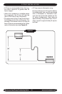
Note: Power should be run to a
weather proof disconnect box usually
within 3 feet of the unit.
ELECTRICAL WIRING
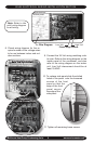
6. From the disconnect box feed the high
Volt wires through a weather proof con-
duit and run the power through the 7/8"
hole (from knock-out) in the unit’s electri-
cal box. Anchor with a strain relief tting.
Refer to the wiring diagram.
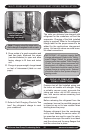
7. Following the wiring diagram, run wires
to the High Volt pigtail in the control box
and attach L1 and L2 connections. Also
run green wire to ground lug.
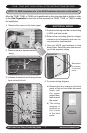
8. Check wiring diagram for the required num-
ber of low voltage wires to be run between
indoor and outdoor sections.
!
!
9. Connect the 24 Volt wiring matching color
to terminal block designation for each zone
as labeled. Refer to the wiring diagram on
the inside front panel of the condenser,
and also refer to the wiring diagram on the
indoor unit. Low Volt interconnect should
be at least 18 AWG.
When connecting to the rear terminal strip
there are two approaches.
a) Using a long straight screw driver over
the top of the front terminal strip while
holding the wire with needle nose pliers
from below.
b) Remove the mounting screw (stubby
screwdriver), then pull the entire front
terminal strip forward, disengaging the
tab on left from slot. When nished,
reinsert terminal strip tab into slot and
reinstall mounting screw.
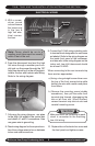
CAUTION
Make sure that Low Volt wiring for each
circuit is connected to the matching
Low Volt wiring.
10. Replace the unit’s electric box cover and
the front panel and tighten screws
.
t2HB, t3HB, And t4HB InStAllAtIon InStructIonS SEctIon
High VoltLow Volt
Knock-out
Mounting
Screw