


www.enviromaster.com
21
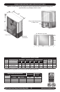
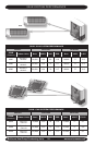
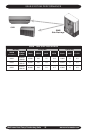
Multi-zone Heat Pump Condensing Units
DFT TST R and DF2
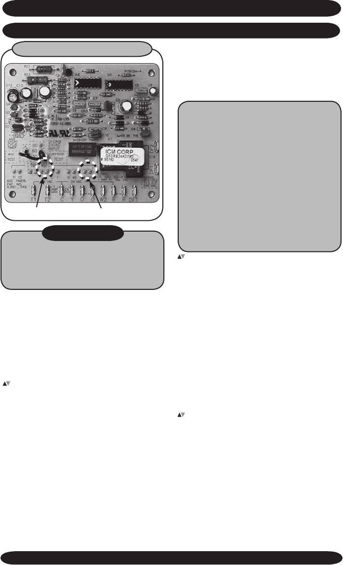
DEFROST CONTROL
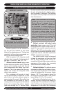
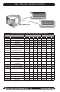
TESTING DEFROST OPERATION USING TEST PINS
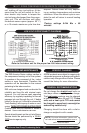
SINGLE-ZONE AND DUAL-ZONE SEQUENCE OF OPERATION
WARNING!
Before removing the access panels to
the unit make sure that all power is dis-
connected from the unit. Failure to do so
could result in injury or electric shock.
Defrost operation can be initiated us-
ing the test pins located on the circuit
board of the condensing unit. “Defrost test
operation” will be a time compressed ver-
sion of the actual defrost cycle.
With the system “off”, using two small
alligator clips, jumper the following sets of
test pins. “R and DF2” and “DFT TST”.
Defrost control board: Apply power
to the indoor and outdoor units. Place the
indoor unit in heating mode with the set
point temperature well above room tem-
perature. This is to ensure that the con-
denser will remain on during the entire
defrost test operation.
The condenser will operate in heat-
ing for approximately 20 seconds. At that
point the unit will enter defrost mode for
approximately 2 seconds. During this time
the condenser fan will switch off, the re-
versing valve will energize and the defrost
board will energize the indoor electric
heat relay through the “W” terminal. After
the two second defrost cycle is complete,
the unit will switch back to heating opera-
tion for another 20 seconds. This process
will repeat until the jumpers are removed
from the test pins.
Note: If the condenser coil is heavily
frosted up with ice, it is likely that the
“Defrost Sensor” is already closed. In
this case the “R and DFT” jumper can
be eliminated. To initiate defrost, mo-
mentarily jump pins marked “DFT TST”
until the defrost cycle begins. The unit
will remain in defrost mode until the
condenser coil is defrosted and then it
will return to heating mode. When test-
ing is complete be sure to remove the
jumper(s). DO NOT leave the unit in
test mode with jumper(s) in place.
Defrost controls with short cycle
protection (heat pumps only): The unit
is equipped with a logic control circuit de-
signed to keep system operating at peek
efciency. The 24V circuit provides control
to the indoor and outdoor systems includ-
ing a three minute, anti-short cycle timer
(ASCT) compressor protection.
The defrost control circuit is designed
to keep the condenser coil free from frost
and ice during heating mode. This is ac-
complished through the precise switching
sequence of the outdoor fan, reversing
valve and indoor auxiliary heater.
Defrost initiation: The defrost-sensor
is located on either the end plate or the re-
turn bend of the condenser coil. A defrost
cycle will initiate after the sensor closes
(approx. 30° F) and remains closed for
the length of time selected on the control
board (either 30, 60 or 90 minutes)*.
At the start of the defrost cycle, the re-
versing valve will change from heating to
cooling mode. The condenser fan will also
switch off, there-by allowing pressure and
temperature to rise within the condenser