


www.enviromaster.comCAC Cassette Evaporator 22
Low Volt Controls
TROUBLESHOOTING PROCEDURE Continued
Cooling Only Units:
Cooling only units require 18awg low Volt
interconnecting wires between the indoor
unit, outdoor units and thermostat. Ter
-
minals designated “Y1” (yellow) and “C”
(brown) of the indoor air handler should
be connected to the corresponding “Y”
(yellow) and “C” (brown) wires or termi-
nals of the outdoor condenser. Other
wire(s) or terminals such as “R” (red) may
not be needed and should be protect from
making contact with the junction box or
other metal surfaces.
Terminals “R”, “Y, “G”, “W” and “C” need
to connect to the indoor, wall mounted
thermostat.
NOTE: “W” is required for units with
electric heat only “C” may not be
needed on some thermostats.
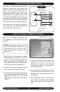
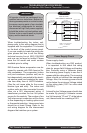
Refer to low Volt interconnect diagram
interconnect diagram figure 1 for remote
thermostat connection.
A 24V transformer located in the indoor
air handler unit provides low Volt control
power to both the indoor air handler and
outdoor condenser. The 24v-power sup
-
ply can be measured by placing a meter
across the “R” and “C” low Volt termi
-
nals of the air handler. The remote wall
mounted thermostat will switch on and off
the condenser through the yellow (Y) and
black (Y1) wires. When the thermostat is
calling for cooling, 24V can be measured
between terminals (wires) Y and C.
The indoor unit contains an electronic anti
short cycle timer feature (ASCT) that will
prevent the outdoor condenser from short
cycling. After the thermostat is satisfied
there will be a three minute delay before
the condenser is allowed to re-start.
Electric Heat:
Units with electric heat utilize a control
relay located on the circuit board in the
control box. As a safety feature, an auto
resetting limit switch located on the heat-
er assembly will interrupt power to the
heater should an over-temperature condi
-
tion occur. Each electric heat assembly is
also equipped with a one time fuse link.
Should electric heat temperatures rise
above the auto resetting limit switch, a
non-resetting, one time fuse link will open
and the heater will remain off. If this oc-
curs the limit switch assembly must be re
-
placed. Contact EMI technical service for
a replacement.
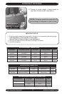
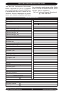
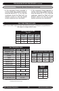
The following current values apply when
the unit is connected to a 230V power
supply. These values include fan motor
current. If the supply power is different,
this will in turn affect the amp draw of the
heater.
5kw = 22.3 amps,
3kw = 13.5 amps,
1.5kw = 6.9 amps.
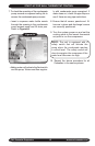
Units with Condensation Pumps:
EMI CAC is equipped with an internal
condensate pump capable of removing
condensate up to a three foot vertical lift.
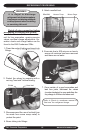
Condensation generated by the evapo
-
rator will collect in the pumps’ reservoir.
When the water level is high enough, a
float switch will close and energize the
pump motor clearing the water from the
reservoir. Should, for any reason, the wa-
ter exceed the maximum preset level, a
safety switch will open, there by interrupt
-
ing the (Y1) signal to the condenser. This
will prevent the evaporator from generat
-
ing additional condensation and spilling
out of the unit.