


Type 99
9
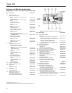
disk or O-ring seat are referenced in Figure 9, part key
numbers unique to the 1000 psig (69,0 bar) maximum
inlet regulator are referenced in Figure 11, and part
key numbers for a Type 61HP (extra high pressure)
pilot is referenced in Figure 12.
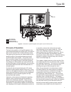
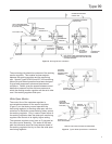
1. Access to all internal actuator parts can be gained
without removing the main valve body from the
line. Disconnect the loading tubing from the
upper casing.
CAUTION
If the regulator has an indicator
assembly, perform the following step
carefully to avoid bending the travel
indicator stem (key 103, Figure 6).
Note
The O-rings and gaskets (keys 111 and
108, Figure 6) in the indicator assembly
are static seals and need not be
disturbed, unless they are leaking.
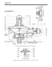
2. Remove the four cap screws (key 58, Figure 9) and
lift off the spring case (key 1, Figure 9). Remove
the travel indicator stem, if any, by unscrewing the
indicator stem adapter (key 101, Figure 6).
3. Remove the main spring seat (key 2, Figure 9)
and main spring (key 3, Figure 9).
4. Remove the 12 cap screws (key 12, Figure 9)
and hex nuts (key 13, Figure 9), and lift off the
upper casing.
5. Remove the diaphragm (key 11, Figure 9) and
diaphragm plate (key 10, Figure 9) by tipping it so
that the lever (key 9, Figure 9) slips out of the
pusher post (key 8, Figure 9).
6. Separate the diaphragm and diaphragm plate by
unscrewing the diaphragm rod (key 4, Figure 9)
from the pusher post. Inspect the diaphragm
(key 11, Figure 9) and pusher post gasket (key 7,
Figure 9). Either part must be replaced if it is
damaged or no longer pliable.
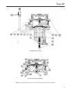
7. If the unit has a stem seal O-ring (key 64,
Figure 7 or 11), this O-ring may be replaced by
removing the retaining ring or cotter pin (key 28,
Figure 9) and disconnecting the lever from the
valve carrier (key 26, Figure 9 or 11), removing
the union nut (key 14, Figure 9 or 11),
disconnecting the pilot supply tubing (key 24,
Figure 9 or 11), and sliding the lower casing
(key 29, Figure 9) away from the valve body
(key 17, Figure 9), with a disk or O-ring seat, the
valve carrier must be pulled out of the lower
casing to gain access to the O-ring. Another
O-ring, held captive by the pressed-in bushing, is
part of the lower casing assembly on a stem seal
unit and normally does not require replacement.
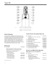
8. If clogging is suspected in the upstream regulator
passages, disconnect the pilot supply tubing
(key 24, Figure 9 or 11), remove the lter assembly
(key 75, Figure 9), and blow through it to check
for lter clogging. If necessary, to clean or replace
lter parts in a standard P590 Series lter
assembly, remove the following as shown in
Figure 10: lter body (key 1), machine screw
(key 4), spring washer (key 6), gasket (key 7),
washer (key 5), and lter element (key 2). Upon
reassembly, one of the at washers must go
between the lter element and lter head (key 3)
and the other must go between the lter element
and gasket.
9. If the lower casing was removed, install a new body
gasket (key 16, Figure 9) and, with a disk or O-ring
seat, slide the valve carrier into the casing. Then
slide the entire assembly into the valve body (disk
or O-ring seat) and secure with the union nut.
Secure the lever to the valve carrier with the
retaining ring or cotter pin.
10. Loosely reassemble the diaphragm and
diaphragm plate so that the bolt holes and
loading connection hole in the diaphragm can
be properly aligned with the corresponding
holes in the casing when the lever is tted
properly into the pusher post. When this
orientation is made, install the collar (key 6,
Figure 9) and tighten the diaphragm rod into the
pusher post (key 8, Figure 9).
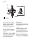
11. In order for the regulator to operate properly, the
assembled collar, diaphragm, diaphragm plate,
pusher post, and diaphragm rod must be
mounted on the ball of the lever so that the
pusher post (key 8, Figure 9) orientation is as
shown in Figure 9.
12. Install the upper casing and secure it to the
lower casing with the twelve cap screws torque
580 to 920 inch-pounds (65,5 to 104 N•m) and hex
nuts. Put lower casing back on body and install
union nut.