


Type 99
8
this recommendation due to the pipe arrangement, it
may be better to make the control line tap nearer the
regulator outlet rather than downstream of a block
valve. Do not make the tap near any elbow, swage, or
nipple which might cause turbulence.
In many instances, it will be necessary to enlarge the
downstream piping to keep ow velocities within good
engineering practices. Expand the piping as close to
the regulator outlet as possible.
!
WARNING
Adjustment of the pilot control spring to
produce an outlet pressure higher than
the upper limit of the outlet pressure
range for that particular spring can cause
personal injury or equipment damage
due to bursting of pressure-containing
parts or the dangerous accumulation
of gases if the maximum actuator
emergency casing pressure in the
Specications section is exceeded. If the
desired outlet pressure is not within the
range of the pilot control spring, install a
spring of the proper range according to
the Maintenance section.
Each regulator is factory-set for the pressure setting
specied on the order. If no setting was specied, outlet
pressure was factory-set at the midrange of the pilot
control spring. In all cases, check the control spring
setting to make sure it is correct for the application.
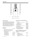
Startup
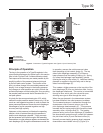
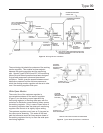
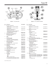
Key numbers are referenced in Figure 9 for a low or
high pressure pilot and in Figure 12 for an extra high
pressure pilot. With proper installation completed and
downstream equipment properly adjusted, perform the
following procedure while using pressure gauges to
monitor pressure.
1. Very slowly open the upstream block valve.
2. Slowly open the hand valve (if used) in the control
line. The unit will control downstream pressure
at the pilot control spring setting. See the
adjustment paragraph following these numbered
steps if changes in the setting are necessary during
the startup procedure.
3. Slowly open the downstream block valve.
4. Slowly close the bypass valve, if any.
5. Check all connections for leaks.
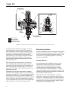
The only adjustment on the regulator is the reduced
pressure setting affected by the pilot control spring
(key 43, Figure 9 or 11). Remove the closing cap
assembly (key 46, Figure 9) and turn the adjusting
screw (key 45, Figure 9 or 11). Turning the adjusting
screw clockwise into the spring case increases the
controlled or reduced pressure setting. Turning
the screw counterclockwise decreases the reduced
pressure setting. Always replace the closing cap, if
used, after making the adjustment.
Shutdown
Isolate the regulator from the system. Vent the
downstream pressure rst; then vent inlet pressure to
release any remaining pressure in the regulator.
Maintenance
Regulator parts are subject to normal wear and must be
inspected and replaced as necessary. The frequency
of inspection and replacement of parts depends on the
severity of service conditions or the requirements of
local, state, and federal rules and regulations.
!
WARNING
Avoid personal injury or damage to
property from sudden release of pressure
or uncontrolled gas or other process uid.
Before starting to disassemble, isolate
the pilot or regulator from all pressure
and cautiously release trapped pressure
from the pilot or regulator. Use gauges to
monitor inlet, loading, and outlet pressures
while releasing these pressures.
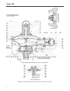
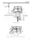
On reassembly of the regulator, it is recommended
that a pipe thread sealant be applied to pressure
connections and ttings as indicated in Figures 7
and 9 and lubricant be applied to sliding and bearing
surfaces as indicated in Figures 7 and 9, and that an
anti-seize compound be applied to adjusting screw
threads and other areas indicated Figures 9 and 11.
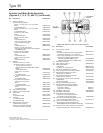
Actuator and Standard P590 Series Filter
This procedure is to be performed if changing the main
spring and spring seat for those of a different range,
or if inspecting, cleaning, or replacing any other parts.
Unless otherwise indicated, part key numbers for a
Type 99 regulator with low or high pressure pilot and