


Type 99
7
location. The line or stack opening must
be protected against condensation,
freezing, and clogging.
Clean out all pipelines before installation and check
to be sure the regulator has not been damaged or
collected foreign material during shipping.
Apply pipe compound to the male pipe threads only with
a screwed body, or use suitable line gaskets and good
bolting practices with a anged body. This regulator
may be installed in any position desired as long as the
ow through the body is in the direction indicated by the
arrow on the body. Install a three-valve bypass around
the regulator if continuous operation is necessary during
maintenance or inspection.
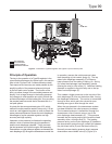
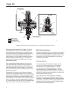
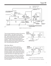
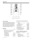
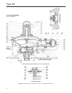
Although the standard orientation of the actuator and
pilot to the main valve body is as shown in Figure 1, this
orientation may be changed as far as the inlet tubing
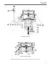
(key 24, Figure 9 or 11) will permit by loosening the
union nut (key 14, Figure 9), rotating the actuator lower
casing (key 29, Figure 9) as desired, and tightening
the union nut. To keep the pilot spring case from being
plugged or the spring case from collecting moisture,
corrosive chemicals, or other foreign material, the vent
must be pointed down, oriented to the lowest possible
point on the spring case, or otherwise protected. Vent
orientation may be changed by rotating the spring
case with respect to the pilot body, or on the extra
high pressure pilot with optional tapped spring case by
rotating the vent with respect to the spring case.
To remotely vent a low pressure pilot, install the vent
line in place of the pressed-in vent assembly (key 60,
Figure 9). Install obstruction-free tubing or piping
into the 1/4-inch (6,35 mm) vent tapping. Provide
protection on a remote vent by installing a screened
vent cap into the remote end of the vent pipe.
To remotely vent a high pressure pilot, or an extra high
pressure pilot with optional tapped spring case, remove
the screwed-in vent assembly (key 72, Figure 9) from
the high pressure pilot spring case or the pressed-in
vent assembly from the extra high pressure pilot
spring case and install obstruction-free tubing or piping
into the 1/4-inch (6,35 mm) vent tapping. Provide
protection on a remote vent by installing a screened
vent cap into the remote end of the vent pipe.
An upstream pilot supply line is not required because
of the integral pilot supply tubing (key 24, Figure 9
or 11). However, as long as the 1/4-inch NPT
tapping in the main valve body is plugged, this
tubing may be disconnected from both the main
valve and lter assembly (key 75, Figure 9) in order
to install a pilot supply line from a desired remote
location into the lter.
If the maximum pilot inlet pressure will be exceeded
by main valve pressure, install a separate reducing
regulator (if not already provided) in the pilot supply line.
A Type 99 regulator has two 1/2-inch threaded NPT
control line pressure taps on opposite sides of the
lower casing (key 29, Figure 9). The regulator normally
comes from the factory with the tap closest to the
regulator outlet left unplugged for the downstream
control line as shown in Figure 1, and with opposite
tap plugged.
Attach the control line from the unplugged tap 2 to
3 feet (0,61 to 0,91 meter) downstream of the regulator
in a straight run of pipe. If impossible to comply with
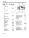
Table 4. Working Monitor Performance
MONITORING PILOT INFORMATION
MINIMUM PRESSURE
AT WHICH WORKING
MONITOR REGULATOR
CAN BE SET
Construction Spring Range
Pilot Spring
Part Number
Wire Diameter,
Inches (cm)
Free Length,
Inches (cm)
Type 161AYW with 1/8-inch
(3,18 mm) port diameter and
150 psig (10,3 bar) maximum
allowable inlet pressure
5 to 15-inches w.c. (12 to 37 mbar)
11 to 28-inches w.c. (27 to 70 mbar)
1B653927022
1B537027052
0.105 (0,27)
0.114 (0,29)
3-3/4 (9,52)
4-5/16 (11,0)
3-inches w.c. (7 mbar)
over normal
distribution pressure
1 to 2.5 psig (0,069 to 0,17 bar)
2.25 to 4.5 psig (0,16 to 0,31 bar)
4.5 to 7 psig (0,31 to 0,48 bar)
1B537127022
1B537227022
1B537327052
0.156 (0,40)
0.187 (0,47)
0.218 (0,55)
4-1/8 (10,5)
3-15/16 (10,0)
4-1/8 (10,5)
0.5 psi (0,03 bar)
over normal
distribution pressure
Type 627-109 with 1/8-inch
(3,18 mm) port diameter and
150 psig (10,3 bar) maximum
allowable inlet pressure for cast
iron body or 750 psig (51,7 bar)
maximum allowable inlet pressure
for malleable iron body
5 to 15 psig (0,34 to 1,03 bar)
10 to 25 psig (0,69 to 1,72 bar)
20 to 35 psig (1,38 to 2,41 bar)
25 to 60 psig (1,72 to 4,14 bar)
1D892327022
1D751527022
1D665927022
1D755527142
0.168 (0,43)
0.187 (0,47)
0.218 (0,55)
0.500 (1,27)
2-15/16 (7,46)
2-13/16 (7,14)
2-15/32 (6,27)
9-1/4 (23,5)
3.0 psi (0,21 bar)
over normal
distribution pressure
40 to 80 psig (2,76 to 5,52 bar)
80 to 150 psig (5,52 to 10,3 bar)
130 to 200 psig (9,00 to 13,8 bar)
1E543627142
1P901327142
(1)
1P901327142
(2)
0.283 (0,72)
0.240 (0,61)
0.240 (0,61)
2-15/16 (7,46)
2-5/8 (6,67)
2-5/8 (6,67)
5.0 psi (0,34 bar)
over normal
distribution pressure
1. With large diaphragm plate.
2. With small diaphragm plate.