


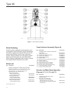
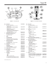
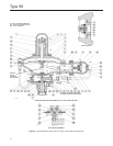
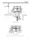

Type 99
6
Installation
!
WARNING
• Personal injury, equipment damage, or
leakage due to escaping gas or
bursting of pressure-containing
parts might result if this regulator
is overpressured or is installed where
service conditions could exceed
the limits for which the regulator was
designed, or where conditions exceed
any ratings of the adjacent piping or
piping connections. To avoid such
injury or damage, provide pressure-
relieving or pressure-limiting devices
(as required by the appropriate code,
regulation, or standard) to prevent
service conditions from exceeding
those limits.
• A regulator may vent some gas to the
atmosphere in hazardous or ammable
gas service, vented gas might
accumulate and cause personal injury,
death or property damage due to re or
explosion. Vent a regulator in
hazardous gas service to a remote,
safe location away from air intakes or
any hazardous location. The vent
line or stack opening must be
protected against condensation
or clogging.
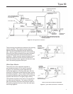
Like most regulators, the Type 99 regulator has a outlet
pressure rating lower than its inlet pressure rating.
Complete downstream overpressure protection is
needed if the actual inlet pressure can exceed the
regulator outlet pressure rating or the pressure ratings
of any downstream equipment. Although the Type H110
relief valve provides sufcient relief capacity to protect
the extra high pressure pilot of the 1000 psig (69,0 bar)
maximum inlet regulator in case the Type 1301F supply
regulator fails open, this protection is insufcient if the
main valve body fails open. Regulator operation within
ratings does not preclude the possibility of damage from
external sources or from debris in the lines. A regulator
should be inspected for damage periodically and after
any overpressure condition.
!
WARNING
The 1000 psig (69,0 bar) maximum
inlet regulator must not be used on
hazardous gas service unless the
Type H110 relief valve can be vented
into a safe area. If vented gas can
accumulate and become a hazard in
enclosed conditions such as in a pit,
underground, or indoors, the relief valve
must be repiped to carry the gas to a
safe location.
A repiped vent line or stack must be
located to avoid venting gas near
buildings, air intakes, or any hazardous
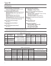
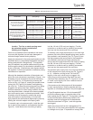
Table 3. Maximum Allowable Drop and Minimum Differential Pressures
MAXIMUM
ALLOWABLE
PRESSURE
DROP, PSIG (bar)
MAIN VALVE SPRING MINIMUM
DIFFERENTIAL
PRESSURE FOR FULL
STROKE, PSIG (bar)
SEAT MATERIAL
MAXIMUM PORT
DIAMETER
(1)
,
INCHES (mm)
Part
Number
Wire Diameter,
Inches (cm)
Free Length,
Inches (cm)
25 (1,72) 1C277127022 0.148 (0,38) 6 (15,2) 0.75 (0,05)
Nitrile (NBR), Neoprene (CR),
Fluorocarbon (FKM)
1-1/8 (28,6)
50 (3,45) 1N801927022 0.156 (0,40) 7-1/8 (18,1) 1.5 (0,10)
Nitrile (NBR), Neoprene (CR),
Fluorocarbon (FKM)
1-1/8 (28,6)
150 (10,3) 1B883327022 0.187 (0,47) 6-5/8 (16,8) 3 (0,21)
Nitrile (NBR), Neoprene (CR),
Fluorocarbon (FKM)
1-1/8 (28,6)
175 (12,1) 1B883327022 0.187 (0,47) 6-5/8 (16,8) 3 (0,21)
Nitrile (NBR)
(2)
, Neoprene (CR)
(2)
,
Fluorocarbon (FKM)
(2)
7/8 (22,2)
250 (17,2)
1B883327022 0.187 (0,47) 6-5/8 (16,8) 3 (0,21) Nitrile (NBR), Fluorocarbon (FKM) 7/8 (22,2)
0W019127022 0.281 (0,71) 6 (15,2) 10 (0,69) Nitrile (NBR)
(3)
, Fluorocarbon (FKM)
(3)
1-1/8 (28,6)
300 (20,7) 0W019127022 0.281 (0,71) 6 (15,2) 10 (0,69) Nylon (PA) 1-1/8 (28,6)
400 (27,6) 0W019127022 0.281 (0,71) 6 (15,2) 10 (0,69) Nylon (PA) 7/8 (22,2)
600 (41,4) 0W019127022 0.281 (0,71) 6 (15,2) 10 (0,69) Nylon (PA) 5/8 (15,9)
1000 (69,0) 0W019127022 0.281 (0,71) 6 (15,2) 10 (0,69) Nylon (PA) 1/2 (12,7)
(4)
1. Can use all port diameters up to maximum size listed.
2. CL125 FF anged body only.
3. O-ring seat only.
4. 1/2-inch (12,7 mm) is the only orice available for 1000 psig (69,0 bar) maximum inlet pressure regulator.