


Quick Installation Guide
00825-0100-4101, Rev EA
June 2010
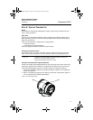
Rosemount 2051
9
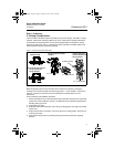
STEP 4: CONNECT THE WIRING AND POWER
Use the following steps to wire the transmitter:
1. Remove the housing cover on the FIELD TERMINALS side.
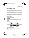
2. Connect the positive lead to the “+” terminal (PWR/COMM) and the negative lead to the
“–” terminal.
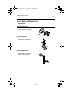
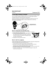
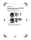
Figure 5. 4–20 mA HART Transmitter Wiring Diagrams
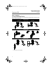
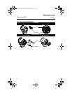
Figure 6. 1-5 Vdc HART Low Power Transmitter Wiring
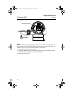
Installation of the transient protection terminal block does not provide transient protection unless the 2051
case is properly grounded.
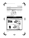
3. Ensure proper grounding. It is important that the instrument cable shield:
• be trimmed close and insulated from touching the transmitter housing.
• be connected to the next shield if cable is routed through a junction box.
• be connected to a good earth ground at the power supply end.
R
L
250
Power
Supply
Power
Supply
Voltmeter
4101_QIG_RevEA.fm Page 9 Tuesday, June 29, 2010 9:26 AM