


Quick Installation Guide
00825-0100-4101, Rev EA
June 2010
Rosemount 2051
14
SAFETY INSTRUMENTED SYSTEMS
The following section applies to 2051 transmitters used in SIS applications.
NOTE
Transmitter output is not safety-rated during the following: configuration changes, multidrop,
loop test. Alternative means should be used to ensure process safety during transmitter
configuration and maintenance activities.
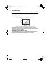
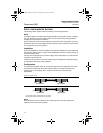
DCS or safety logic solver must be configured to match transmitter configuration. Figure 10
identifies the two alarm level available and their operation values. Position the alarm switch
to the required HI or LO alarm position.
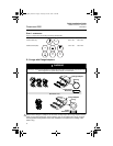
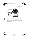
Installation
No special installation is required in addition to the standard installation practices outlined in
this document. Always ensure a proper seal by installing the electronics housing cover(s) so
that metal contacts metal.
The loop must be designed so the terminal voltage does not drop below 10.5 Vdc when the
transmitter output is 22.5 mA.
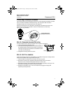
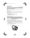
Position the security switch to the “ON” position to prevent accidental or deliberate change
of configuration data during normal operation.
Configuration
Use any HART-compliant master to communicate with and verify configuration of the 2051.
User-selected damping will affect the transmitters ability to respond to changes in the
applied process. The damping value + response time must not exceed the loop
requirements.
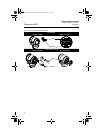
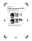
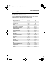
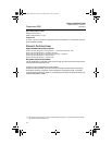
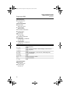
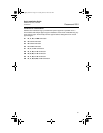
Figure 10. Alarm Levels
NOTE
Some detected faults are indicated on the analog output at a level above high alarm
regardless of the alarm switch selection.
Rosemount Alarm Level
Namur Alarm Level
(1) Transmitter Failure, hardware alarm in LO position.
(2) Transmitter Failure, hardware alarm in HI position.
Normal Operation
4 mA
20 mA
20.8 mA
high saturation
21.75
(2)
3.9 mA
low saturation
3.75
mA
(1)
Normal Operation
4 mA
20 mA
20.5 mA
high saturation
22.5
(2)
3.8 mA
low saturation
3.6 mA
(1)
4101_QIG_RevEA.fm Page 14 Tuesday, June 29, 2010 9:26 AM