


Quick Installation Guide
00825-0100-4101, Rev EA
June 2010
Rosemount 2051
7
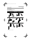
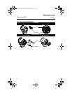
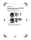
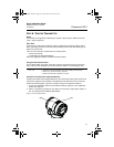
E. Inline Gage Transmitter Orientation
The low side pressure port (atmospheric reference) on the inline gage transmitter is located
in the neck of the transmitter, behind the housing. The vent path is 360° around the
transmitter between the housing and sensor. (See Figure 3.)
Keep the vent path free of any obstruction, including but not limited to paint, dust, and
lubrication by mounting the transmitter so that the contaminants can drain away.
Figure 3. Inline Gage Transmitter
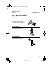
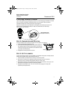
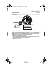
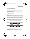
STEP 2: CONSIDER HOUSING ROTATION
To improve field access to wiring or to better view the optional LCD display:
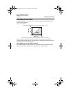
STEP 3: SET THE JUMPERS
If alarm and security jumpers are not installed, the transmitter will operate normally with the
default alarm condition alarm high and the security off.
1. If the transmitter is installed, secure the loop, and remove power.
2. Remove the housing cover opposite the field terminal side. Do not remove the
instrument cover in explosive atmospheres when the circuit is live.
3. Reposition the jumper. Avoid contact with the leads and the terminals. See Figure 4 for
the location of the jumper and the ON and OFF positions.
4. Reattach the transmitter cover. The cover must be fully engaged to comply with
explosion-proof requirements.
1. Loosen the housing rotation set screw.
2. First rotate the housing clockwise to the desired location. If
the desired location cannot be achieved due to thread limit,
rotate the housing counter clockwise to the desired location
(up to 360° from thread limit).
3. Retighten the housing rotation set screw.
Low side pressure port
(atmospheric reference)
Housing Rotation Set Screw
(5/64-inch)
4101_QIG_RevEA.fm Page 7 Tuesday, June 29, 2010 9:26 AM