


Table of Contents
Chapter 1 Introduction ................................................ 1
Introduction......................................................................... 1
Features ........................................................................... 1
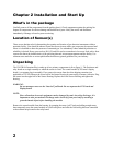
Chapter 2 Installation and Start Up ..................................... 2
What’s in the package ................................................................ 2
Location of Sensor(s) ................................................................. 2
Unpacking ......................................................................... 2
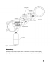
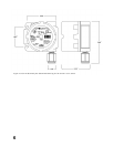
Figure 1 Toxic Detector Layout .................................................. 3
Mounting........................................................................... 3
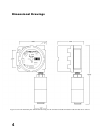
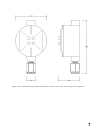
Figure 2 Uni-Tran Premium plus dimensional drawing for the ST1200 ST1300 ST1400 ST1500
ST1600 toxic sensors. ................................................... 4
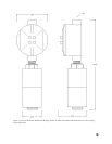
Figure 3 Uni-Tran Premium dimensional drawing for the ST1200 ST1300 ST1400 ST1600 toxic
sensors using sensor separation. .......................................... 5
Figure 4 Uni-Tran Premium plus dimensional drawing for the ST1210 toxic sensor. . . . . . . . . . 6
Figure 5 Uni-Tran Premium plus dimensional drawing for the ST1210 toxic sensor using sensor
separation. ............................................................ 7
Wiring ... ... ...... ...... ...... ...... ...... ...... ...... ...... ...... ...... ......... .. 8
Figure 6 Display Board Layout ................................................... 9
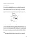
Sensor Separation............................................................. 9
Figure 7 Uni-Tran Premium Plus wiring drawing for the ST1400 toxic sensor . . . . . . . . . . . . . . 11
Figure 8 Uni-Tran Premium Plus wiring drawing for the St1400 toxic sensor using sensor
separation............................................................ 12
Figure 9 Uni-Tran Premium Plus wiring diagram for the ST1200, ST1300, ST1500 and ST1600
Toxic Sensors ........................................................ 13
Figure 10 Uni-Tran Premium Plus wiring drawing for the ST1200, ST1300 , ST1500 and ST1600
toxic sensor using sensor separation....................................... 14
Figure 11 Uni-Tran Premium Plus wiring drawing for the ST1210 toxic sensor . . . . . . . . . . . . . 15
Figure 12 Uni-Tran Premium Plus wiring drawing for the ST1210 toxic sensor using sensor
separation............................................................ 16
Figure 13 Display Board Layout ................................................. 17
Installation Checklist................................................................. 17
Start Up .......................................................................... 17
Relay Settings ............................................................... 18
Table 1 - Default Relay Settings ................................................. 18
Main Menu ................................... 18
Figure 14 - Magnetic Reed Switch Activation ....................................... 19
Summary of Main Menu ....................................................... 19
Review Settings.............................................................. 20
Chapter 3 System Calibration ........................................ 20
Calibration Procedure................................................................ 21
Figure 15 - Magnetic Reed Switch Activation ....................................... 21
2
Calibration Procedure for UNI-TRAN Premium Plus ST1400 O sensor . . . . . . . . . . . . . . . . . . . . . . . . 22
Periodic Response Check ............................................................ 23
Chapter 4 Operation ................................................ 23
Operator Interface .................................................................. 23
Main Menu.................................................................. 23
Figure 16 - Magnetic Reed Switch Activation ....................................... 23
Summary of Main Menu ....................................................... 24
Table 2 - Table of Responses ................................................... 24
Calibration Procedure ......................................................... 24