


17
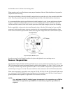
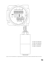
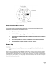
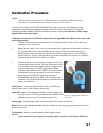
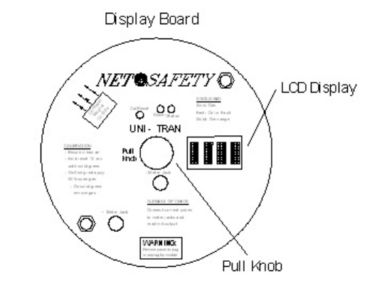
Figure 13 Display Board Layout
Installation Checklist
The following checklist is provided for double checking the system to be sure that all phases of system
installation are complete and have been performed correctly.
T Toxic Detector is securely mounted
T All cable shields are properly grounded, at one end only
T Explosion proof conduit seals have been installed at all conduit entries (if conduit is
being used)
T Power wiring to the Toxic Detector is installed and power source is operational
T External loads are properly connected to the Toxic Detector
Start Up
WARNING
Confirm that power is removed before inserting or removing the Control Module from the relay
board.
(Refer to figure 13) With power applied, check that the green Power LED is On, there is a message scrolling
on the LCD display and the Status LED is flashing (slow) red. After 90 seconds the Status LED will change
from flashing red to a short green blip every 2 seconds. During power up, the LCD display scrolls the message
“Start Delay Uni-Tran Net Safety”. The analog output will be 3.0mA during the start delay and will change to
4.0mA after the 90 second start delay.