


8
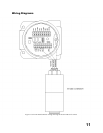
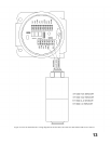
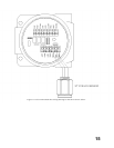
Wiring
(refer to figure 7, 8, 9, 10, 11 and 12)
NOTE:
The wiring procedures in this manual are intended to ensure proper functioning of the device
under normal conditions. However, because of the many variations in wiring codes and
regulations, total compliance to these ordinances cannot be guaranteed. Confirm that all
wiring complies with applicable regulations that relate to the installation of electrical
equipment in a hazardous area. If in doubt, consult a qualified official before wiring the
system.
NOTE
The control module (CPU board and Display Board) with cable should never be totally removed
from the Relay board and housing. If it is removed there are bright red alignment markings on the
cable and on the Relay board for you to use when re-inserting the cable into the Relay Board
connector.
NOTE
Since all modern electronic equipment can be damaged by static electricity discharge it is
important to discharge static electricity from your body by touching a grounded metal object before
handling the module.
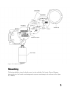
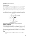
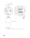
Refer to figure 1
The transmitter is made up of two assemblies. The enclosure / relay board are a single assembly to which the
input is wired. The control module (CPU board and Display Board) is a separate assembly. To conduct wiring
unscrew the two retaining screws from the front of the display board . (The control module is attached to the
relay board by a cable. Do not detach the cable during wiring). Detach the module from the housing by
grasping the centre (Pull Here) knob and pull straight away. Gently hang the module from the cable while you
conduct wiring.
The use of shielded cable is highly recommended for signal, input, output and power wires to protect against
interference caused by extraneous electrical 'noise'. Relay outputs do not require shielded cable. In
applications where the wiring cable is installed in conduit, the conduit must not be used for wiring to other
electrical equipment. The maximum distance between the sensor and controller is limited by the resistance of
the connecting wiring, which is a function of the gauge of the wire being used. Refer to the manuals on the
sensors used (and transmitters if used) for maximum wiring distances and wiring instructions (refer to
Appendix B).
NOTE:
The controller contains semiconductor devices that are susceptible to damage by electrostatic
discharge. An electrostatic charge can build up on the skin and discharge when an object is
touched. Therefore, use caution when handling, taking care not to touch the terminals or
electronic components. For more information on proper handling, refer to the Appendix A.
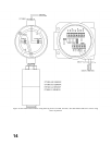
Water-proof and explosion-proof conduit seals are recommended to prevent water accumulation within the
enclosure. Seals should be located as close to the device as possible and not more than 18 inches (46 cm)
away. Explosion-proof installations may require an additional seal where conduit enters a