


13
MAN-0076 Rev 05 Millennium II
December 07, 2012
Net Safety Monitoring Inc
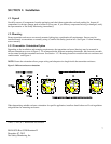
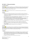
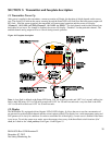
Warning Before wiring, ensure that power to transmitter is switched off.
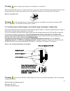
When connecting cable wires, use a small screwdriver to gently press down and hold the spring connector open. Insert
the appropriate wire into the open connector hole, releasing the screwdriver to secure the wire. See Figure 6.
Figure 6: Connecting wires
Warning Avoid touching electronic components, as they are susceptible to electrostatic discharge (ESD).
Refer to Appendix A, “Electrostatic Sensitive Device (ESD)”.
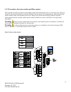
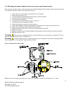
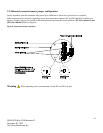
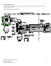
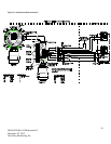
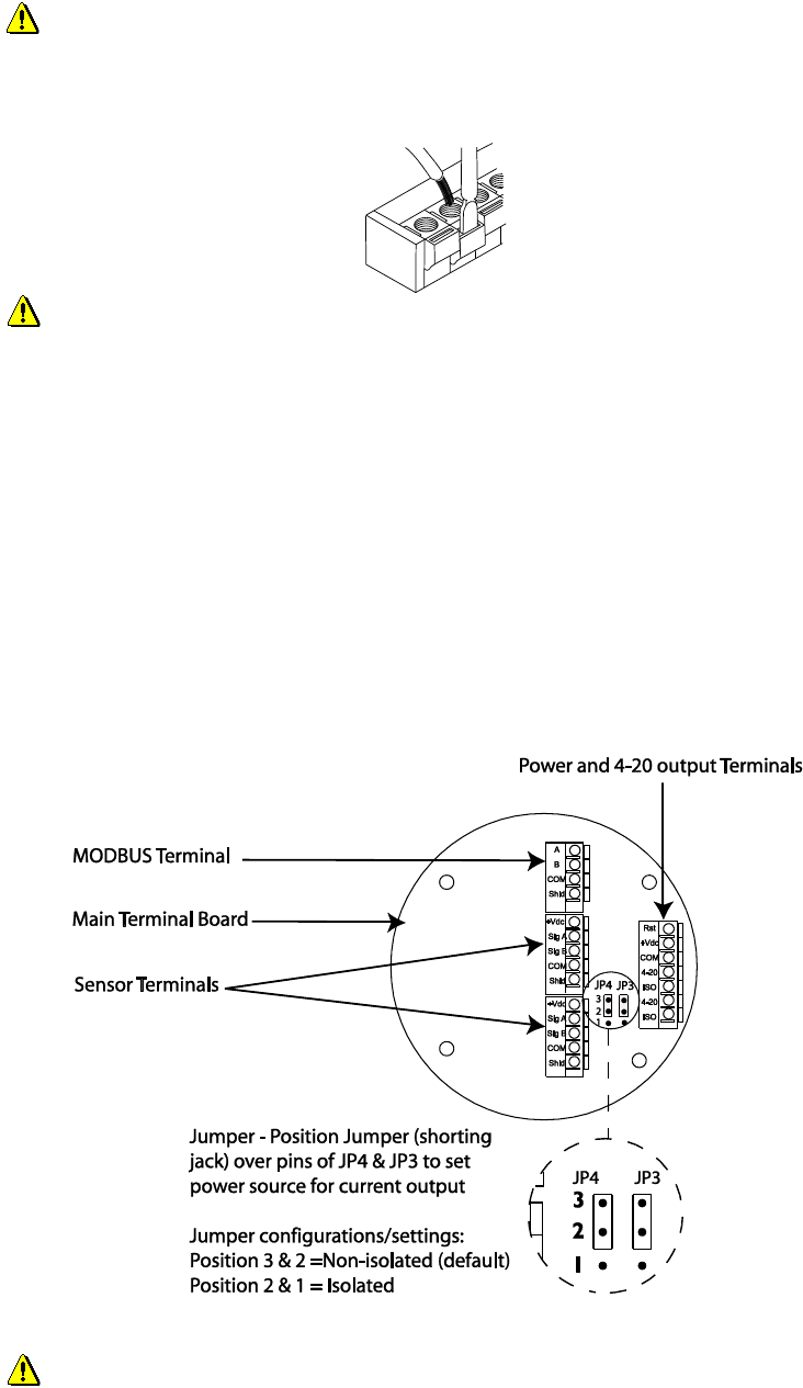
2.1.3 Analog output, isolated supply, non-isolated supply and jumper configuration
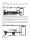
The analog output may be powered from the main instrument power supply or a separate, independent power supply in
which case an isolated wiring configuration is necessary.
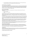
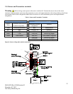
To set a Non-isolated or Isolated current output, simply move the Jumpers/shorting jacks (JP3 and JP4) to either the
Non-isolated or Isolated current position. For Non-isolated current output, ensure pins 3 & 2 at JP3 & JP4
location on the main terminal board are jumpered (shorted). Factory standard models ship with jumpers at JP3 &
JP4 in the Non-isolated current output position (default position).
For Isolated current output, pins 1 & 2 at JP3 & JP4 should be jumpered (shorted). Note that JP3 is for
configuring channel 1 and JP4 is for configuring channel 2. Jumpers and pins are located next to the Power and 4-
20 output terminals on the main terminal board. See Figure 7, also Figure 12 & Figure 13 for reference.
Figure 7: Non- Isolated and Isolated current jumpers
Warning Always ensure that JP3 and JP4 jumpers are in the correct position depending on the current output
configuration chosen.