


12
MAN-0076 Rev 05 Millennium II
December 07, 2012
Net Safety Monitoring Inc
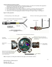
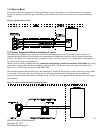
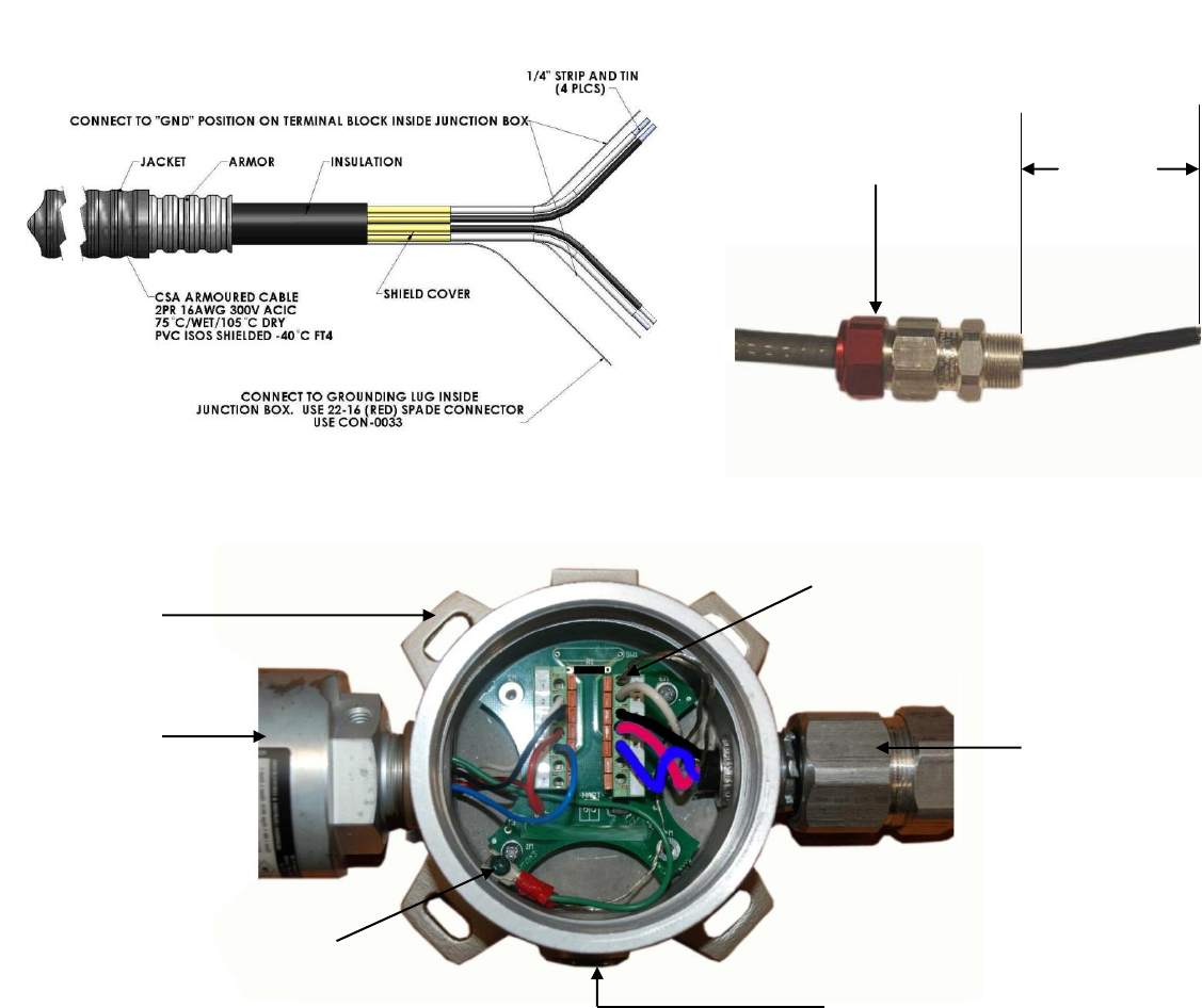
Armored Cable preparation procedure:
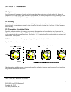
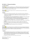
1. Prepare the armored instrument cable as illustrated in Figure 5 and follow all assembly and/or preparation
instructions provided by the cable and/or cable gland manufacturer.
2. Install cable gland and reducer onto the cable.
3. Ensure four (4) inches of wire length is available for connecting to terminals inside the junction box.
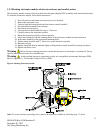
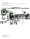
4. Use a small flat head screw driver when connecting wires to connector terminals. See Figure 6.
5. Connect sensor wires to the appropriate terminals. See Figure 5C, Figure 9, Figure 12 and Figure 13.
Figure 5: Cable preparation
Note: If required, use cable glands which have been approved for hazardous locations.
4 Inches
Hazloc cable gland
A: Drawing showing of cable without gland
B. Picture of cable showing gland and insulation
C. Picture of cable wired to junction box and sensor
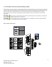
Millennium II
Sensor
Cable gland &
Armored cable
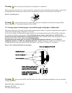
Shield wires from each twisted pair
connected to “GND” (Earth Ground) on
terminal block.
Shield wire from flexible Armored
cable and sensor ground wire (Green
wire) connected to Earth grounding
screw in junction box
¾” NPT stopping
plug.
Net Safety
Junction Box