


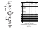
7. Screw in three 40-watt (maximum) can-
delabra base round bulbs into the sock-
ets in the motor housing (Figure 16).
8. Screw in two 40-watt (maximum) can-
delabra base bulbs into the light fitter
sockets (Figure 17).
9. Place the lower glass over the thread-
ed nipple and seat the glass in the light
fitter adapter (Figure 17). Position the
decorative cap over the threaded nip-
ple and then securely install the finial
nut.
10. Your ceiling fan is now installed and
wired to be controlled by your remote
control system.
To avoid possible fire or shock, make
sure that the electrical wires are
completely inside the outlet box and
not pinched between the ceiling
cover and the ceiling.
!
WARNING
10
11
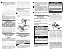
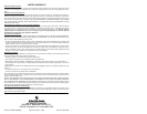
STANDARD ON-OFF WALL
SWITCH OR OPTIONAL SW115
WALL CONTROL
BLACK
BLACK
WHITE
BLACK
BLACK
WHITE
HANGER BALL
GREEN WIRE (GROUND)
FROM HANGER BALL AND
HANGER BRACKET
TWO-CONDUCTOR
CABLE (WITH
GROUND)
BLACK
(HOT)
WHITE
GROUND
TO
120-
VOLT
SUPPLY
WHITE
BLUE
BLUE
ORANGE
ORANGE
WHITE
Figure 14
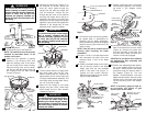
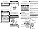
3. Push the wires and connectors up into
the outlet box while inserting the receiv-
er fully into the hanger bracket. Position
the antenna wire on top of the receiver.
4. Screw the two 1-1/4” threaded studs
(supplied) into the tapped holes in the
hanger bracket (Figure 13).
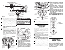
5. Lift the ceiling cover up to the threaded
studs and turn until the studs protrude
through the holes in the ceiling cover
(Figure 15).
6. Secure the ceiling cover in place by
sliding lockwashers (supplied) over the
threaded studs and installing the two
knurled knobs (supplied). (Figure 15).
Tighten the knurled knobs securely
until the ceiling cover fits snugly against
the ceiling.
LOCKWASHER (2)
KNURLED
KNOB (2)
THREADED
STUD (2)
CEILING
COVER
Figure 15
PLATE
LIGHT
FITTER
DECORATIVE
CAP
FINIAL NUT
LOWER
GLASS
THREADED
NIPPLE
40-WATT CANDELABRA
BASE BULB (2)
Figure 17
40-WATT CANDELABRA
BASE ROUND BULB (3)
MOTOR
HOUSING
SOCKET
Figure 16
Operating Your
Ceiling Fan
IMPORTANT
Fan installation must be completed,
including the installation of the fan
blades, before testing of the remote
control.
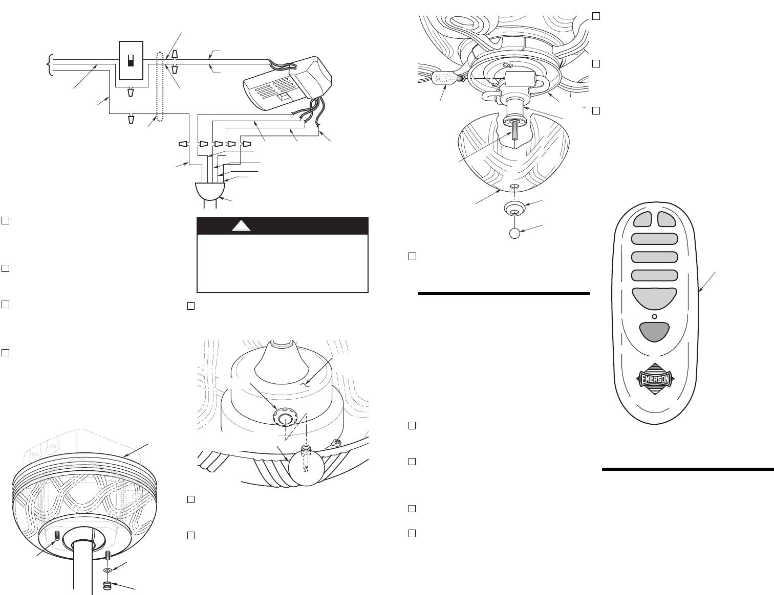
Your remote control (Figure 18) has full
control of your fan and light.
1. Restore electrical power to the outlet
box by turning the electricity on at the
service panel.
2. To set the desired fan speed, press the
HIGH, MED, or LOW buttons to oper-
ate your fan on high, medium, or low
speed.
3. To turn your fan off, press the OFF
button.
4. To change the airflow direction of the
fan blades, press the REV button. The
direction the fan blades turn will change
each time the REV button is pressed.
®
OFF
REV
LOW
MED
HIGH
UP DN
REMOTE
CONTROL
TRANSMITTER
Figure 18
Installation of
Storage Bracket
A storage bracket is supplied with the
remote control for holding the transmitter
when not in use. If you desire to use the
bracket, use the two screws (supplied)
and install it on a wall that is away from
excess heat or humidity.
5. To turn the downlight on, press and
release the DN button. The light will
turn on at the light intensity previously
selected.
6. To turn the uplight on, press and
release the UP button. The light will
turn on at the light intensity previously
selected.
7. To vary the intensity of the light, hold
the DN or UP button down until the
desired light intensity is reached, then
release the button.
Red light should turn on when any but-
ton is pressed. If the light does not
come on, replace the battery.