


9
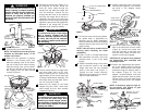
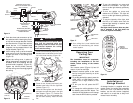
1. Position the supply wires to the left side
of the outlet box (Figure 13); position
the fan wires to the right side. Partially
insert the remote control receiver (flat
side up) until one end rests on the
hanger ball as shown in Figure 13.
NOTE: Make all wiring connections
using wire connectors (supplied). Make
sure that all connections are tight,
including ground, and that no bare wire
is visible at the wire connectors, except
for the ground wire.
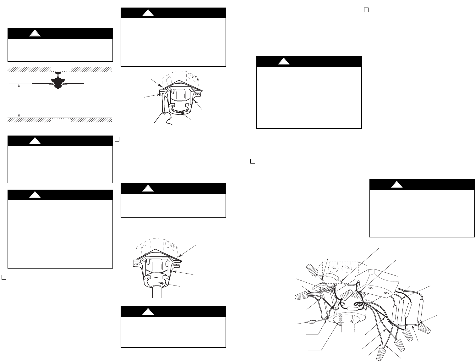
2. Carefully lift the fan and seat the hang-
er ball/downrod assembly on the hang-
er bracket that was just attached to the
outlet box (Figure 12). Be sure the
groove in the ball is lined up with the
tab on the hanger bracket (Figure 11).
8
How to Hang
Your Ceiling Fan
How to Wire
Your Ceiling Fan
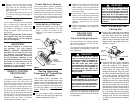
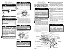
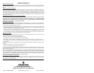
The fan must be hung with at least 7'
of clearance from floor to blades
(Figure 10).
!
WARNING
The outlet box and joist must be
securely mounted and capable of
supporting at least 50 lbs. Use only a
U.L. outlet box listed as “Acceptable
for Fan Support”.
!
WARNING
To reduce the risk of fire, electric
shock, or personal injury, mount fan
to outlet box marked “Acceptable for
Fan Support”, and use screws sup-
plied with outlet box. Most outlet
boxes commonly used for support of
light fixtures are not acceptable for
fan support and may need to be
replaced. Consult a qualified electri-
cian if in doubt.
!
WARNING
FLOOR
CEILING
AT LEAST
7'
Figure 10
1. Securely attach the hanger bracket to
the outlet box using the two screws
supplied with the outlet box (Figure 11).
Hanger bracket must seat firmly
against outlet box. If the outlet box is
recessed, remove wall board until
bracket contacts box. If bracket
and/or outlet box are not securely
attached, the fan could wobble or
fall.
!
WARNING
Failure to seat tab in groove could
cause damage to electrical wires and
possible shock or fire hazard.
!
WARNING
Turning off wall switch is not suffi-
cient. To avoid possible electrical
shock, be sure electricity is turned off
at the main fuse box before wiring. All
wiring must be in accordance with
National and Local codes and the ceil-
ing fan must be properly grounded as
a precaution against possible electri-
cal shock.
!
WARNING
To avoid possible fire or shock, do
not pinch wires between the hanger
ball/downrod assembly and hanger
bracket.
!
WARNING
Check to see that all connections are
tight, including ground, and that no
bare wire is visible at the wire con-
nectors, except for the ground wire.
Do not operate fan until blades are in
place. Noise and fan damage could
result.
!
WARNING
TWO SCREWS
SUPPLIED
WITH
OUTLET BOX
HANGER
BRACKET
TAB
OUTLET
BOX
NOTE: CEILING COVER, SUPPLY WIRES AND FAN
WIRES OMITTED FOR CLARITY.
OUTLET
BOX
HANGER
BRACKET
HANGER BALL/
DOWNROD
ASSEMBLY
Figure 11
Figure 12
If you feel that you do not have enough
electrical wiring knowledge or experi-
ence, have your fan installed by a
licensed electrician.
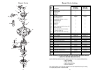
2. Refer to Figure 13 and 14 and connect
the receiver wires to the supply wires
and the fan motor wires as follows:
a. Securely connect the green grounding
wires from the hanger ball and the
hanger bracket to the supply grounding
conductor (this may be a bare wire or a
wire with green insulation).
b. Securely connect the supply white
(neutral) wire to the receiver white
(AC IN N) wire.
c. Securely connect the supply black wire
(hot) wire to the receiver black (AC IN
L) wire.
d. Securely connect the fan motor white
wire to the receiver white (TO MOTOR
N) wire.
e. Securely connect the fan motor black
wire to the receiver black (TO MOTOR
L) wire.
f. Securely connect the fan motor blue
wire to the receiver blue (FOR
BOTTOM LIGHT) wire.
g. Securely connect the fan motor orange
wire to the receiver orange (FOR
UPPER LIGHT) wire.
GREEN GROUND WIRE
FROM HANGER BRACKET
RECEIVER BLACK
WIRE
RECEIVER WHITE
WIRE
FAN WHITE WIRE
ANTENNA
A
C
I
N
N
AC IN L
FOR BOTTOM LIGHT
TO MOTOR N
RECEIVER
BLUE WIRE
RECEIVER BLACK WIRE
RECEIVER WHITE
WIRE
SUPPLY WHITE WIRE
(NEUTRAL)
SUPPLY BLACK
WIRE (HOT)
GROUND WIRE
GREEN GROUND WIRE
FROM HANGER BALL
FAN BLUE WIRE
1-1/4" THREADED
STUD (2)
TO MOTOR L
FAN BLACK
WIRE
FOR UPPER LIGHT
RECEIVER
ORANGE WIRE
FAN ORANGE
WIRE
Figure 13
CAUTION: To reduce the risk of electri-
cal shock, disconnect the electrical
supply circuit before installing the fan,
light kit or receiver.