


WARNING: To avoid fire, shock, and serious personal injury, follow these
instructions.
Safety Instructions
1. Read your owner’s manual carefully and keep it for future reference.
2. Before servicing or cleaning unit, switch power off at service panel and
lock service panel disconnecting means to prevent power from being
switched on accidentally. When the service disconnecting means cannot
be locked, securely fasten a warning device, such as a tag, to the service
panel.
3. Be careful of the fan and blades when cleaning, painting, or working near
the fan. Always turn off the power to the ceiling fan before servicing.
4. Do not put anything into the fan blades while they are turning.
5. Do not operate reversing switch until fan blades have come to a complete
stop.
Additional Safety Instructions for Installation
1. To avoid possible shock, be sure electricity is turned off at the fuse box
before wiring, and do not operate fan without blades.
2. The installation is to be in accordance with the National Electrical Code,
ANSI/NFPA 70-1999 and Local Codes. Use the National Electrical Code if
Local Codes do not exist. The ceiling fan must be grounded as a precau-
tion against possible electrical shock. Electrical installation should be
made or approved by a licensed electrician.
3. The outlet box and joist must be securely mounted and capable of reliably
supporting at least 50 pounds. Use only U.L. outlet boxes listed as
“Acceptable for Fan Support”, and use the mounting screws provided with
the outlet box. Most outlet boxes commonly used for support of light fix-
tures are not acceptable for fan support and may need to be replaced.
Consult a qualified electrician if in doubt.
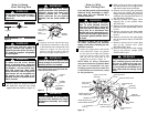
4. The downrod furnished with the fan provides the minimum recommended
floor to fan blade clearance for an 8 foot ceiling.
5. The fan must be mounted with the fan blades at least 7 feet from the floor
to prevent accidental contact with the fan blades.
6. Follow the recommended instructions for the proper method of wiring
your ceiling fan. If you do not know enough about electrical wiring, have
your fan installed by a licensed electrician.
NOTE: This fan is suitable for use with solid-state speed controls.
WARNING: To reduce the risk of fire or electric shock, this fan should only be used
with fan speed control Model No. UL7067RC, manufactured by Rhine Electric Co., Ltd.
WARNING: This product is designed to use only those parts supplied with this
product and/or any accessories designated specifically for use with this product by
Emerson Electric Co. Substitution of parts or accessories not designated for use with
this product by Emerson Electric Co. could result in personal injury or property
damage.
WARNING: To reduce the risk of personal injury, do not bend the blade flange when
installing the blade flanges, balancing the blades or cleaning the fan. Do not insert
foreign objects in between rotating fan blades.
!
WARNING
DATE CODE:
The date code of this fan may be found on the box, stamped in ink on a white label.
You should record this data above and keep it in a safe place for future use.
2
3
Tools Needed for Assembly
One Phillips head screwdriver
One wire stripper
One stepladder
Six wire connectors (supplied)
Materials
Wiring, outlet box and box connectors
must be of type required by the local code.
The minimum wire would be a 3-conductor
(2-wire with ground) of the following sizes:
Installed Wire Length Wire Size A.W.G.
Up to 50 ft. 14
50-100 ft. 12
This Manual Is Designed to Make it as Easy as Possible for You to
Assemble, Install, Operate and Maintain Your Ceiling Fan
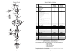
Unpacking Instructions
For your convenience, check-off boxes
are provided next to each step. As each
step is completed, place a check mark
in the box. This will insure that all steps
have been completed and will be help-
ful in finding your place should you be
interrupted.
Do not install or use fan if any part is
damaged or missing. Call Toll-Free:
1-800-654-3545
!
WARNING
This product is designed to use only
those parts supplied with this product
and/or any accessories designated
specifically for use with this product by
Emerson Electric Co. Substitution of
parts or accessories not designated for
use with this product by Emerson Electric
Co. could result in personal injury or
property damage.
!
WARNING
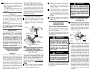
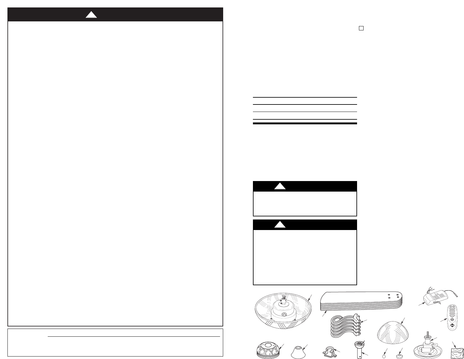
a. Fan motor and housing assembly
b. One ceiling cover
c. One coupling cover
d. Five fan blades
e. Five blade flanges
f. One hanger bracket
g. One hanger ball/downrod assembly
h. One decorative cap
i. One finial nut
j. One lower glass
k. One adapter/light fitter assembly
l. One remote control transmitter
m. One remote control receiver
n. One loose parts bag, containing:
1. Two 1-1/4” threaded studs
2. Two knurled knobs
3. Two lockwashers
4. Six wire connectors
5. One hairpin clip
6. One clevis pin
7. Eleven 1/4-20 x 11mm pan head
screws with lockwashers
8. Twenty-one 10-24 x 9mm truss
head screws
9. Twenty-one fiber washers
10. Four 8-32 x 12mm pan head screws
NOTE: Place the parts from the loose
parts bags in a small container to keep
them from being lost. If any parts are
missing, contact your local retailer or
catalog outlet for replacement before
proceeding.
A
D
B
C
J
I
H
K
N
E
G
F
L
®
OFF
REV
LOW
MED
HIGH
UP DN
M
1. Open styrofoam unit containing fan.
Remove top half of styrofoam unit.
Remove parts and check to see that
you have received the following parts:
NOTE: If you are uncertain of part
description, refer to exploded view
illustration.