


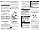
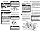
2. Slide the four switch levers on the code
switch to your choice of ON (up) or
down positions. Use a ball-point pen or
small screwdriver and slide the levers
firmly up or down.
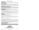
3. In the receiver (Figure 1), slide the four
switch levers to the same positions as
set in the transmitter. Make sure the
levers on both switches are in the same
positions, otherwise the fan will not
operate.
4. Position the battery in the transmitter
battery compartment and replace the
battery cover.
CEILING FAN
PROCEDURES
Electrical Requirements
Your new ceiling fan will require a ground-
ed electrical supply line of 120 volts AC,
60 Hz, 15 amp circuit.
The outlet box must be securely anchored
and capable of withstanding a load of at
least 50 pounds.
Preset Memory Feature
Your remote control receiver is equipped
with a preset memory feature. The receiv-
er will remember the light intensity and fan
speed when the light and fan are turned off
from the wall switch. When the wall switch
is turned back on, the lights and fan will
resume operation as they were prior to the
switch being turned off.
Installation of Battery
1. Remove the battery cover and install
four AAA alkaline batteries (not sup-
plied), oriented as shown in the
diagram in the battery compartment.
(Figure 1).
2. Remove the fan motor and housing
assembly from the protective plastic
bag. Place the fan assembly into the
upper foam pad with the top of the
motor facing up.
The upper foam pad serves as a hold-
er for the fan during the first stages of
assembly.
General
Your Emerson ceiling fan comes equipped
with a remote control transmitter and a
remote control receiver. This remote con-
trol systems is designed to control your
ceiling fan speed, airflow direction, and
light intensity.
NOTE: An optional SW115 Wall Control
(not supplied) may also be used with
the remote control receiver supplied
with your ceiling fan.
IMPORTANT
This Owner’s Manual is divided into
two sections. The first section,
REMOTE CONTROL PROCEDURES,
describes how to install the four alka-
line batteries (not supplied) in the
remote control transmitter, and how to
set the operating frequency of the
transmitter and receiver. These instruc-
tions must be performed prior to the
installation of the ceiling fan as
described in the second section,
CEILING FAN PROCEDURES.
REMOTE CONTROL
PROCEDURES
General
The remote control system is designed to
separately control your ceiling fan and
light intensity. There are four push buttons
on the transmitter (HIGH, MED, LOW,
OFF) to set the fan speed and turn the fan
off. The REV push button changes the air-
flow direction of the fan blades. The UP
(uplight) and DN (downlight) push buttons
turn the lights on and off and controls the
light intensities. The red indicator light will
illuminate while any button is pressed,
indicating that the battery is good.
4
5
REMOTE
CONTROL
TRANSMITTER
CODE
SWITCH
1 2 3 4
ON
BATTERY COVER
SWITCH LEVERS
AAA
AAA
AAA
AAA
RECEIVER
Setting Operating
Frequency of Transmitter
and Receiver
Your remote control transmitter and
receiver have code switches which must
be set on one of 16 possible code combi-
nations. The four levers (numbered 1, 2, 3,
and 4) on the switches are factory-set in
the ON (up) position. Do not use this
setting. Change the switch settings as
follows:
1. On the remote control transmitter,
locate the code switch just above the
battery compartment (Figure 1).
To reduce the risk of fire, electric
shock, or personal injury, mount fan
to outlet box marked “Acceptable for
Fan Support”, and use screws sup-
plied with outlet box. Most outlet
boxes commonly used for support of
light fixtures are not acceptable for
fan support and may need to be
replaced. Consult a qualified electri-
cian if in doubt.
!
WARNING
Turning off wall switch is not suffi-
cient. To avoid possible electrical
shock, be sure electricity is turned off
at the main fuse box before wiring. All
wiring must be in accordance with
National and Local codes and the ceil-
ing fan must be properly grounded as
a precaution against possible electri-
cal shock.
!
WARNING
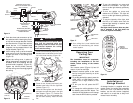
How to Assemble Your
Ceiling Fan
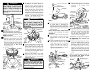
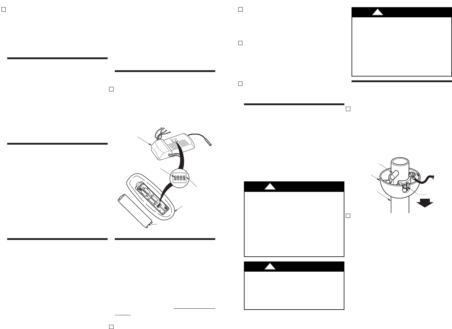
1. Remove the hanger ball by loosening
the setscrew in the hanger ball until the
ball falls freely down the downrod
(Figure 2). Remove the pin from the
downrod, then remove the hanger ball.
Retain the pin and hanger ball for rein-
stallation in step 5.
2. Unscrew the two upper setscrews
(Figure 3) until they clear the inside of
the motor coupling. Then separate,
untwist and unkink the three 80” motor
leads. Route the motor lead wires
through the downrod. Align the clevis
pin holes in the downrod with the holes
in the motor coupling. Install the clevis
pin and secure with the hairpin clip
(Figure 3). The clevis pin must go
through the holes in the motor coupling
and the holes in the downrod. Be sure
to push the straight leg of the hairpin
clip through the hole near the end of
the clevis pin until the curved portion of
the hairpin clip snaps around the clevis
pin. The hairpin clip must be properly
installed to prevent the clevis pin from
working loose. Pull up on the downrod
to make sure the clevis pin is properly
installed.
PIN
HANGER
BALL
SETSCREW
DOWNROD
Figure 2
Figure 1
To avoid possible fire or shock, fol-
low all wiring instructions carefully.
Any electrical work not described in
these instructions should be done or
approved by a licensed electrician.
!
WARNING
If your fan is to replace an existing ceiling
light fixture, turn electricity off at the main
fuse box at this time and remove the exist-
ing light fixture.