


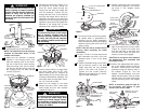
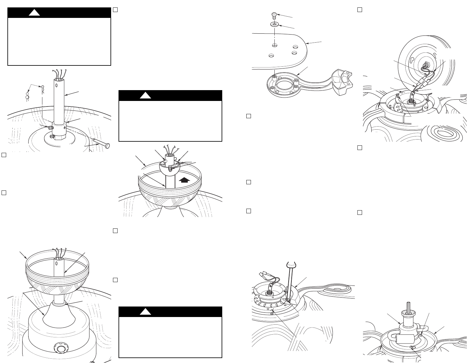
11. Partially install two 8-32 x 12mm pan
head screws (supplied) in two thread-
ed holes in the adapter holder
(Figure 8).
12. Connect the white wire from the light
fitter to the white wire from the motor
(Figure 8). Connect the black wire
from the light fitter to the black wire
from the motor. Make sure both con-
nectors are securely engaged.
CAUTION: Do not pinch wires between
the adapter/light fitter assembly and
the adapter holder.
13. Position the adapter/light fitter assem-
bly on the adapter holder so that the
two 8-32 x 12mm screws in the holder
protrude through the keyhole slots in
the adapter (Figure 9). Turn the
adapter counterclockwise and then
tighten the two screws. Securely install
another 8-32 x 12mm pan head screw
into the remaining hole in the adapter
holder.
NOTE: If necessary, grasp the light fit-
ter and gently turn slightly to gain
access to the screw heads.
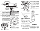
8. Turn the fan motor and housing assem-
bly upside down in preparation for
mounting the fan blade assemblies.
Remove and discard the three shipping
retainers securing the motor hub in the
motor housing.
NOTE: Take care not to scratch the fan
housing when installing the blade
assemblies.
9. Insert a 1/4-20 x 11mm pan head screw
with lockwasher into each of the two
recessed holes in one of the blade
flanges.
10. Position the blade flange on the motor
hub so that the screws in the blade
flange align with the two threaded
holes in the motor hub (Figure 7).
Tighten the two screws securely.
Repeat this procedure for the remain-
ing four blade assemblies.
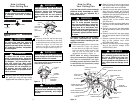
5. Reinstall the hanger ball (Figure 5) on
the downrod as follows. Route the
three 80” motor leads through the
hanger ball and slide the hanger ball
over the downrod. Position the pin
through the two holes in the downrod
and align the hanger ball so the pin is
captured in the groove in the top of the
hanger ball. Pull the hanger ball up tight
against the pin and securely tighten the
setscrew in the hanger ball. A loose
setscrew could create fan wobble.
6. The fan comes with blue, orange, black
and white leads that are 80” long.
Before installing the fan, measure up
approximately 6 to 9-inches above top
of hanger ball/downrod assembly. Cut
off excess leads and strip back insula-
tion 1/2” from end of leads.
7. Mount the fan blades to the blade
flanges using four 10-24 x 9mm truss
head screws and four fiber washers
(supplied) (Figure 6).
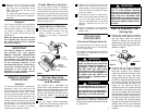
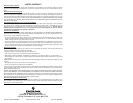
3. Tighten the setscrews (Figure 3) secure-
ly while pulling up on the downrod.
NOTE: The setscrews must be properly
installed as described above, or fan
wobble could result.
4. Make sure the grommet is properly
installed in the coupling cover, then
slide the coupling cover on the down-
rod until it rests on the motor housing.
Place the ceiling cover over the down-
rod. Be sure that the ceiling cover and
the coupling cover are both oriented
correctly (Figure 4).
BLADE FLANGE
1/4-20 x 11mm PAN
HEAD SCREW WITH
LOCKWASHER (2)
MOTOR HUB
Figure 7
INSTALL 8-32 x 12mm
PAN HEAD SCREW
ADAPTER
LIGHT FITTER
ASSEMBLY
TIGHTEN TWO PAN
HEAD SCREWS
Figure 9
LIGHT FITTER
WHITE WIRE
LIGHT FITTER
BLACK WIRE
MOTOR
WHITE WIRE
8-32 x 12mm PAN HEAD
SCREWS (2)
MOTOR
BLACK WIRE
ADAPTER
HOLDER
Figure 8
7
It is critical that the clevis pin in the
motor coupling is properly installed
and the setscrew securely tightened.
Failure to verify that the pin and
setscrew are properly installed (as
shown in Figure 3) could result in the
fan falling.
!
WARNING
It is critical that the pin in the hanger
ball is properly installed and the
setscrew securely tightened. Failure
to verify that the pin and setscrew
are properly installed could result in
the fan falling.
!
WARNING
To reduce the risk of personal injury,
do not bend the blade flange when
installing the blade flanges, balanc-
ing the blades or cleaning the fan. Do
not insert foreign objects in between
rotating fan blades.
!
WARNING
DOWNROD
HAIRPIN
CLIP
SETSCREW (2)
MOTOR
COUPLING
CLEVIS PIN
Figure 3
SETSCREW
HANGER BALL
PIN
CEILING
COVER
DOWNROD
Figure 5
DOWNROD
CEILING COVER
COUPLING
COVER
GROMMET
Figure 4
FAN BLADE
10-24 X 9mm TRUSS HEAD
SCREW (4)
FIBER WASHER (4)
BLADE FLANGE
Figure 6
6