


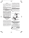
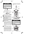
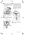
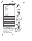
2. Carefully lift the fan and seat the hang-
er ball/downrod assembly on the hang-
er bracket that was just attached to the
outlet box (Figure 11). Be sure the
groove in the ball is lined up with the
tab on the hanger bracket (Figure 10).
8
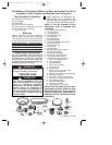
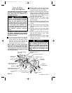
How to Hang
Your Ceiling Fan
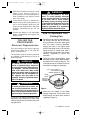
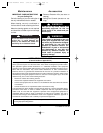
The fan must be hung with at least 7'
of clearance from floor to blades
(Figure 9).
!
WARNING
The outlet box and joist must be
securely mounted and capable of
supporting at least 50 lbs. Use only a
U.L. outlet box listed as “Acceptable
for Fan Support”.
!
WARNING
To reduce the risk of fire, electric
shock, or personal injury, mount fan
to outlet box marked “Acceptable for
Fan Support”, and use screws sup-
plied with outlet box. Most outlet
boxes commonly used for support of
light fixtures are not acceptable for
fan support and may need to be
replaced. Consult a qualified electri-
cian if in doubt.
!
WARNING
CEILING
AT LEAST
7'
FLOOR
Figure 9
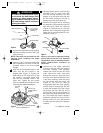
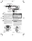
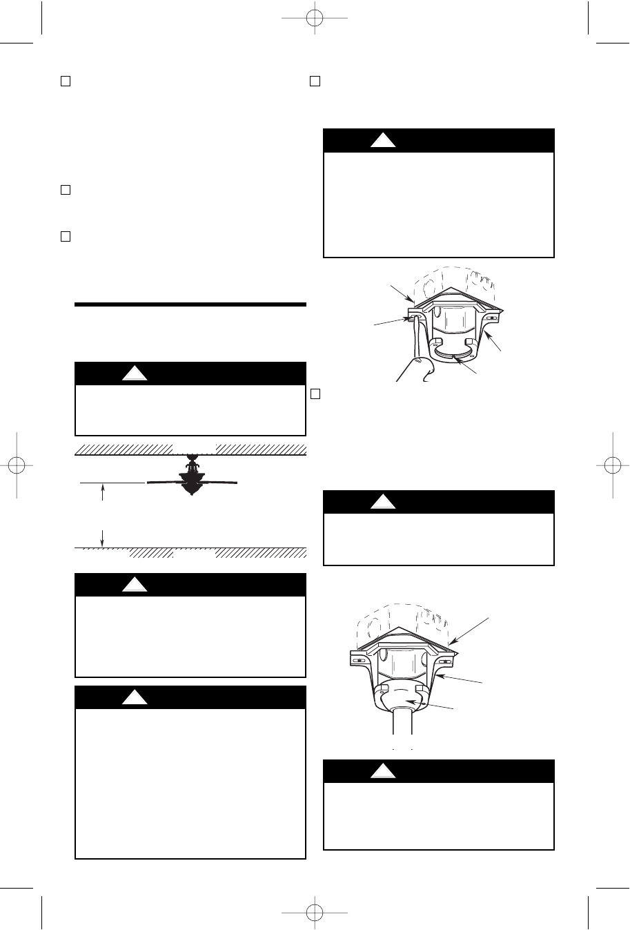
1. Securely attach the hanger bracket to
the outlet box using the two screws
supplied with the outlet box (Figure 10).
Hanger bracket must seat firmly
against outlet box. If the outlet box is
recessed, remove wall board until
bracket contacts box. If bracket
and/or outlet box are not securely
attached, the fan could wobble or
fall.
!
WARNING
Failure to seat tab in groove could
cause damage to electrical wires and
possible shock or fire hazard.
!
WARNING
To avoid possible fire or shock, do
not pinch wires between the hanger
ball/downrod assembly and hanger
bracket.
!
WARNING
TWO SCREWS
SUPPLIED
WITH
OUTLET BOX
HANGER
BRACKET
TAB
OUTLET
BOX
NOTE: CEILING COVER, SUPPLY WIRES AND FAN
WIRES OMITTED FOR CLARITY.
OUTLET
BOX
HANGER
BRACKET
HANGER BALL/
DOWNROD
ASSEMBLY
Figure 10
Figure 11
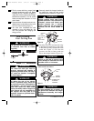
13. The fan comes with blue, orange, black
and white leads that are 80” long. Before
installing the fan, measure up approxi-
mately 6 to 9-inches above top of hanger
ball/downrod assembly. Cut off excess
leads and strip back insulation 1/2” from
end of leads.
14. Screw the three 40-watt (maximum) can-
delabra base round bulbs into the sock-
ets in the motor housing (Figure 7).
15. You have now completed the initial
assembly of your new ceiling fan. You
can now proceed with hanging and
wiring your fan.
U.L. Model No.: CF160
BP7358 RUSTICO CF160 9/19/07 11:23 AM Page 8