


General
Your Emerson ceiling fan comes equipped
with a remote control transmitter and a
remote control receiver. This remote con-
trol systems is designed to control your
ceiling fan speed, airflow direction, and
light intensity.
NOTE: An optional SW115 Wall Control
(not supplied) may also be used with
the remote control receiver supplied
with your ceiling fan.
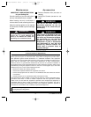
IMPORTANT
This Owner’s Manual is divided into
two sections. The first section,
REMOTE CONTROL PROCEDURES,
describes how to install the four alka-
line batteries (not supplied) in the
remote control transmitter, and how to
set the operating frequency of the
transmitter and receiver. These instruc-
tions must be performed prior to the
installation of the ceiling fan as
described in the second section,
CEILING FAN PROCEDURES.
REMOTE CONTROL
PROCEDURES
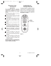
General
The remote control system is designed to
separately control your ceiling fan and
light intensity. There are four push buttons
on the transmitter (HIGH, MED, LOW,
OFF) to set the fan speed and turn the fan
off. The REV push button changes the air-
flow direction of the fan blades. The UP
(uplight) and DN (downlight) push buttons
turn the lights on and off and controls the
light intensities. The red indicator light will
illuminate while any button is pressed,
indicating that the battery is good.
Preset Memory Feature
Your remote control receiver is equipped
with a preset memory feature. The receiv-
er will remember the light intensity and fan
speed when the light and fan are turned off
from the wall switch. When the wall switch
is turned back on, the lights and fan will
resume operation as they were prior to the
switch being turned off.
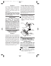
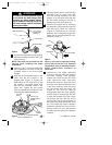
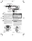
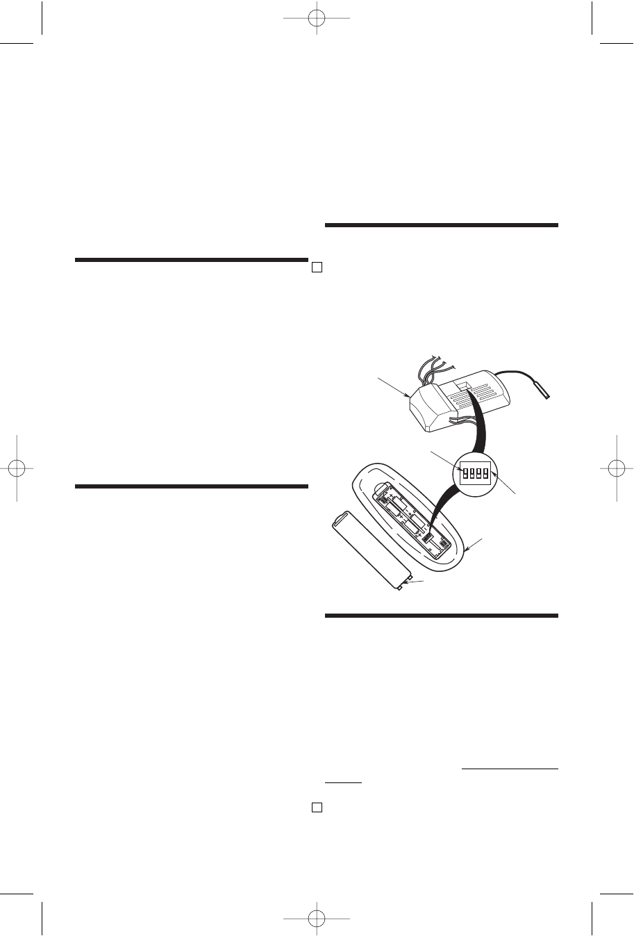
Installation of Battery
1. Remove the battery cover and install
four AAA alkaline batteries (not sup-
plied), oriented as shown in the
diagram in the battery compartment.
(Figure 1).
4
REMOTE
CONTROL
TRANSMITTER
CODE
SWITCH
1 2 3 4
ON
BATTERY COVER
SWITCH LEVERS
AAA
AAA
AAA
AAA
RECEIVER
Setting Operating
Frequency of Transmitter
and Receiver
Your remote control transmitter and
receiver have code switches which must
be set on one of 16 possible code combi-
nations. The four levers (numbered 1, 2, 3,
and 4) on the switches are factory-set in
the ON (up) position. Do not use this
setting. Change the switch settings as
follows:
1. On the remote control transmitter,
locate the code switch just above the
battery compartment (Figure 1).
Figure 1
U.L. Model No.: CF160
BP7358 RUSTICO CF160 9/19/07 11:23 AM Page 4