


7. Carefully remove the fan motor housing
assembly from the lower foam pad.
Turn the housing assembly over and
position it on the lower foam pad with
the fan blades resting on the pad so
that the top of the motor faces up.
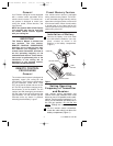
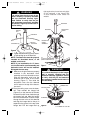
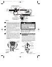
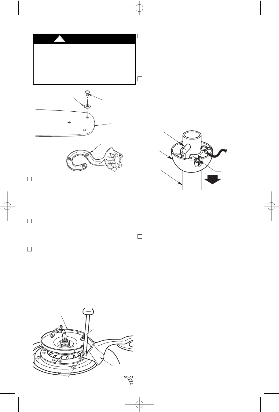
8. Remove the hanger ball by loosening
the setscrew in the hanger ball until the
ball falls freely down the downrod
(Figure 5). Remove the pin from the
downrod, then remove the hanger ball.
Retain the pin and hanger ball for rein-
stallation in step 12.
NOTE: If you have an eight-foot ceiling,
you will have to use the 3-1/2” downrod
(supplied) in order to maintain the nec-
essary blade-to-floor clearance of
seven feet.
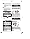
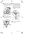
9. Unscrew the two upper setscrews
(Figure 6) until they clear the inside of
the motor coupling. Then separate,
untwist and unkink the four 80” motor
leads. Route the motor lead wires
through the downrod. Align the clevis
pin holes in the downrod with the holes
in the motor coupling. Install the clevis
pin and secure with the hairpin clip
(Figure 6). The clevis pin must go
through the holes in the motor coupling
and the holes in the downrod. Be sure
to push the straight leg of the hairpin
clip through the hole near the end of
the clevis pin until the curved portion of
the hairpin clip snaps around the clevis
pin. The hairpin clip must be properly
installed to prevent the clevis pin from
working loose. Pull up on the downrod
to make sure the clevis pin is properly
installed.
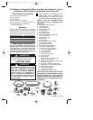
4. Remove and discard the three shipping
retainers securing the motor hub in the
motor housing.
NOTE: Take care not to scratch the fan
housing when installing the blade
assemblies.
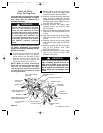
5. Insert a 1/4-20 x 11mm pan head screw
with lockwashers into each of the two
recessed holes in one of the blade
flanges.
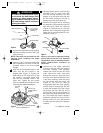
6. Align two of the threaded holes in the
motor with the two cutouts in the
adapter plate (Figure 4). Position the
blade flange on the motor hub so that
the screws in the blade flange align
with the two threaded holes in the
motor hub. Tighten the two screws
securely. Repeat this procedure for the
remaining four blade assemblies.
6
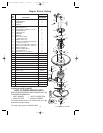
FAN BLADE
BLADE FLANGE
10-24 X 9mm
TRUSS HEAD
SCREW (3)
FIBER WASHER (3)
Figure 3
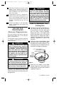
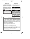
To reduce the risk of personal injury,
do not bend the blade flange when
installing the blade flanges, balanc-
ing the blades or cleaning the fan. Do
not insert foreign objects in between
rotating fan blades.
!
WARNING
CUTOUT FOR
FLANGE SCREW
ACCESS
BLADE
FLANGE
1/4-20 x 11mm PAN HEAD SCREW
WITH LOCKWASHER (2)
ADAPTER
PLATE
PIN
HANGER
BALL
SETSCREW
DOWNROD
Figure 5
Figure 4
U.L. Model No.: CF160
BP7358 RUSTICO CF160 9/19/07 11:23 AM Page 6