


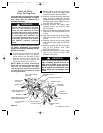
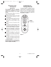
2. Slide the four switch levers on the code
switch to your choice of ON (up) or
down positions. Use a ball-point pen or
small screwdriver and slide the levers
firmly up or down.
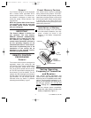
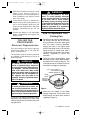
3. In the receiver (Figure 1), slide the four
switch levers to the same positions as
set in the transmitter. Make sure the
levers on both switches are in the same
positions, otherwise the fan will not
operate.
4. Position the battery in the transmitter
battery compartment and replace the
battery cover.
CEILING FAN
PROCEDURES
Electrical Requirements
Your new ceiling fan will require a ground-
ed electrical supply line of 120 volts AC,
60 Hz, 15 amp circuit.
The outlet box must be securely anchored
and capable of withstanding a load of at
least 50 pounds.
5
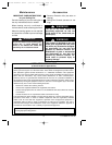
To reduce the risk of fire, electric
shock, or personal injury, mount fan
to outlet box marked “Acceptable for
Fan Support”, and use screws sup-
plied with outlet box. Most outlet
boxes commonly used for support of
light fixtures are not acceptable for
fan support and may need to be
replaced. Consult a qualified electri-
cian if in doubt.
!
WARNING
Turning off wall switch is not suffi-
cient. To avoid possible electrical
shock, be sure electricity is turned off
at the main fuse or circuit breaker
box before wiring. All wiring must be
in accordance with National and Local
codes and the ceiling fan must be
properly grounded as a precaution
against possible electrical shock.
!
WARNING
How to Assemble Your
Ceiling Fan
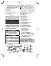
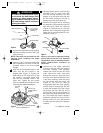
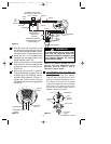
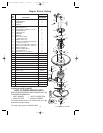
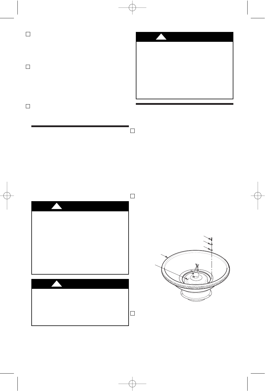
1. Place the motor housing assembly on a
flat surface with the top of the motor
facing upwards. Place the upper glass
over the motor housing assembly,
aligning the slots in the upper glass
with the mounting holes in the housing
flange (Figure 2). Install three 8-32 x
15mm screws, flat washers, and rubber
washers (supplied) to secure the
assembly.
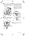
2. Place the motor housing/upper glass
assembly onto the lower foam pad with
the bottom of the motor facing you. The
lower pad serves as a holder for the fan
during the first stages of assembly.
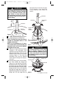
3. Mount the fan blades to the blade
flanges using three 10-24 x 9mm truss
head screws and three fiber washers
(supplied) (Figure 3).
8-32 x 15mm SCREW (3)
FLAT WASHER (3)
RUBBER WASHER (3)
UPPER
GLASS
MOTOR
HOUSING
ASSEMBLY
Figure 2
To avoid possible fire or shock, fol-
low all wiring instructions carefully.
Any electrical work not described in
these instructions should be done or
approved by a licensed electrician.
!
WARNING
If your fan is to replace an existing ceiling
light fixture, turn electricity off at the main
fuse box at this time and remove the exist-
ing light fixture.
U.L. Model No.: CF160
BP7358 RUSTICO CF160 9/19/07 11:23 AM Page 5