


7
UL Model No.: CF144 & CF152
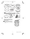
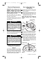
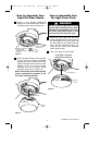
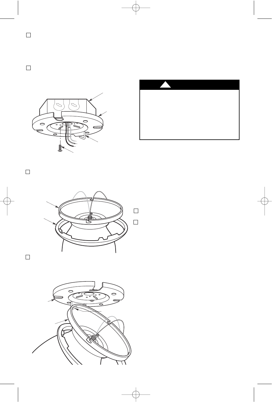
2. Pull the electrical supply black, white
and ground wires through the center
opening of the ceiling mounting plate
before securing the plate to the outlet
box (Figure 6).
3. Position the ceiling mounting plate onto
the outlet box and secure using the two
outlet box screws, supplied with outlet
box (Figure 6).
Figure 6
OUTLET BOX
SCREWS (2)
CEILING
MOUNTING
PLATE HOOK
CEILING
MOUNTING
PLATE
OUTLET
BOX
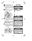
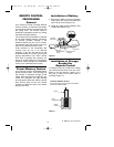
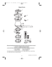
4. Slide the ceiling trim ring over the fan
motor assembly and let it rest on the
motor assembly (Figure 7).
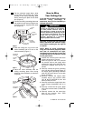
5. Place the motor assembly onto the
ceiling mounting plate hook during
wiring fan motor assembly to outlet box
(Figure 8).
CEILING
TRIM
RING
FAN MOTOR
ASSEMBLY
Figure 7
FAN MOTOR
ASSEMBLY
HOOK
CEILING
MOUNTING
PLATE
Figure 8
How to Wire
Your Ceiling Fan
Turning off wall switch is not sufficient.
To avoid possible electrical shock, be
sure electricity is turned off at the main
fuse box before wiring. All wiring must be
in accordance with National and Local
codes and the ceiling fan must be
properly grounded as a precaution
against possible electrical shock.
!
WARNING
If you feel that you do not have enough
electrical wiring knowledge or
experience, have your fan installed by a
licensed electrician.
CAUTION: To reduce the risk of electrical
shock, disconnect the electrical supply
circuit before installing the fan, light kit
or receiver.
NOTE: Make all wiring connections
using wire connectors (supplied). Make
sure that all connections are tight,
including ground, and that no bare wire
is visible at the wire connectors, except
for the ground wire.
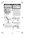
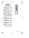
1. Position the receiver into the fan motor
housing as shown in Figure 9.
2. Refer to Figures 9 and 10 to connect
the receiver wires to the supply wires
and the fan motor wires using the wire
connectors supplied with the fan as
follows:
a. Securely connect the green grounding
wire from the ceiling mounting plate to
the supply green grounding conductor
(this may be a bare wire or a wire with
green insulation).
b. Securely connect the supply white
(neutral) wire to the receiver white
(AC IN N)/(TO MOTOR N) wire and
white (neutral) fan wire.
c. Securely connect the supply black wire
to the receiver black/white (AC IN L)
wire.
d. Securely connect the fan motor black
wire to the receiver black (TO MOTOR
L) wire.
e. Securely connect the fan motor blue
wire to the receiver blue (FOR
BOTTOM LIGHT) wire.
BP7407 44" & 52" Curva Sky 1/11/10 9:54 PM Page 7