


3
THE FAN MODELS CF144BS, CF144CRM, CF152BS & CF152CRM ARE SUITABLE
FOR DAMP LOCATIONS SUCH AS COVERED PORCHES, COVERED PATIOS,
AND COVERED DECKS...ANYWHERE THERE IS A ROOF OVERHEAD.
THE FAN MODELS CF144WW, CF144ORB, CF152WW & CF152ORB ARE
SUITABLE FOR WET LOCATIONS SUCH AS PORCHES, PATIOS, AND DECKS.
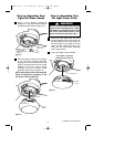
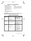
This Manual is Designed to Make it as Easy as Possible for You to
Assemble, Install, Operate and Maintain Your Ceiling Fan
Do not install or use fan if any part is
damaged or missing. Call Toll-Free:
1-800-654-3545
!
WARNING
This product is designed to use only
those parts supplied with this product
and/or any accessories designated
specifically for use with this product by
Emerson Electric Co. Substitution of
parts or accessories not designated for
use with this product by Emerson Electric
Co. could result in personal injury or
property damage.
!
WARNING
Tools Needed for Assembly
One Phillips head screwdriver
One wire stripper
One stepladder
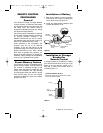
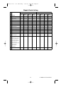
Materials
Wiring, outlet box and box connectors
must be of type required by the local code.
The minimum wire would be a 3-conductor
(2-wire with ground) of the following sizes:
Installed Wire Length Wire Size A.W.G.
Up to 50 ft. 14
50-100 ft. 12
Before assembling your ceiling fan, refer
to section on proper method of wiring
your fan (Page 7). If you feel you do not
have enough wiring knowledge or
experience, have your fan installed by a
licensed electrician.
!
WARNING
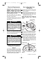
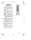
Unpacking Instructions
For your convenience, check-off boxes are provided next to each step. As each
step is completed, place a check mark in the box. This will insure that all steps
have been completed and will be helpful in finding your place should you be
interrupted.
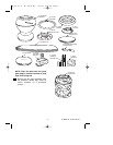
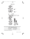
NOTE: If you are uncertain of part
description, refer to exploded view
illustration.
a. Fan motor assembly
b. One ceiling trim ring
c. One ceiling mounting plate
d. Three fan blades
e. One lower housing
f. One light kit plate
g. One glass shade
h. One no-light cover plate
i. One 6-speed electronic receiver
control with parts bag
j. One 6-speed handheld transmitter
with wall bracket
k. Two 50W halogen mini candelabra
bulbs
l. One loose parts bag containing:
1. Three 12 ga. wire connectors
2. One spare M5 x 10mm pan head
ceiling cover screw
3. Ten M5 x 16mm flange head
blade screws
4. One spare M4 x 10mm pan head
screw for lower housing and
light kit
5. One balancing kit
1. Open carton containing fan. Remove
top half of styrofoam unit. Remove
parts and check to see that you have
received the following parts:
UL Model No.: CF144 & CF152
BP7407 44" & 52" Curva Sky 1/11/10 9:54 PM Page 3