


5
Your new ceiling fan will require a
grounded electrical supply line of 120 volts
AC, 60 Hz, 15 amp circuit.
The outlet box must be securely anchored
and capable of withstanding a load of at
least 50 pounds.
General
Your Emerson ceiling fan comes supplied
with a Fan/Light Remote Control which
consists of a receiver mounted inside the
ceiling cover of the fan motor housing.
This system allows you to regulate your
ceiling fan speed and light intensity.
To reduce the risk of fire, electric shock,
or personal injury, mount fan to outlet box
marked “Acceptable for Fan Support”,
and use screws supplied with outlet box.
Most outlet boxes commonly used for
support of light fixtures are not
acceptable for fan support and may need
to be replaced. Consult a qualified
electrician if in doubt.
!
WARNING
If your fan is to replace an existing ceiling
light fixture, turn electricity off at the main
fuse or circuit breaker box at this time and
remove the existing light fixture.
IMPORTANT: Your ceiling fan will not
function properly, and may be
damaged, if used with any wall dimmer
switch or control other than the
Emerson Electric Fan/Light Remote
Control supplied with the fan.
Electrical Requirements
Ceiling Fan Procedures
How to Assemble Your
Ceiling Fan
Turning off wall switch is not sufficient.
To avoid possible electrical shock, be
sure electricity is turned off at the main
fuse or circuit breaker box before wiring.
All wiring must be in accordance with
National and Local codes and the ceiling
fan must be properly grounded as a
precaution against possible electrical
shock.
!
WARNING
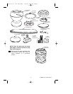
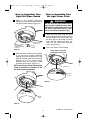
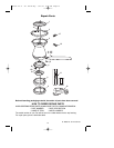
UL Model No.: CF144 & CF152
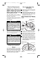
SLIDE FAN BLADE
INTO BLADE
CENTER SLOT
FAN
BLADE
M5 x 16mm FLANGE
HEAD BLADE SCREWS
(3 per blade)
BLADE
SLOT
FAN
HOUSING
Figure 1
1. Position the fan motor assembly upside
down in preparation for mounting the
three fan blades.
2. Slide blade through blade slot in fan
housing assembly. Mount blade to fan
housing using three M5 x 16mm flange
head blade screws (Figure 1).
3. Complete the remaining two blades
installation per the above instructions.
NOTE: Take care not to scratch fan
housing assembly when installing
blades.
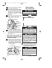
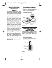
4. Remove one of the three screws in the
motor housing assembly and loosen
the remaining two screws (Figure 2).
5. Attach the lower housing assembly to
the fan motor using the two key slot
holes (Figure 2). Secure the lower
housing assembly by tightening the two
screws. Reinstall the screw that was
previously removed.
REMOVE M4 x 10mm
PAN HEAD SCREW
LOWER HOUSING
KEY HOLE
SLOT (2)
Figure 2
BP7407 44" & 52" Curva Sky 1/11/10 9:54 PM Page 5